6A-7POWER TRIM90-13645--2 495
Wiring Diagram
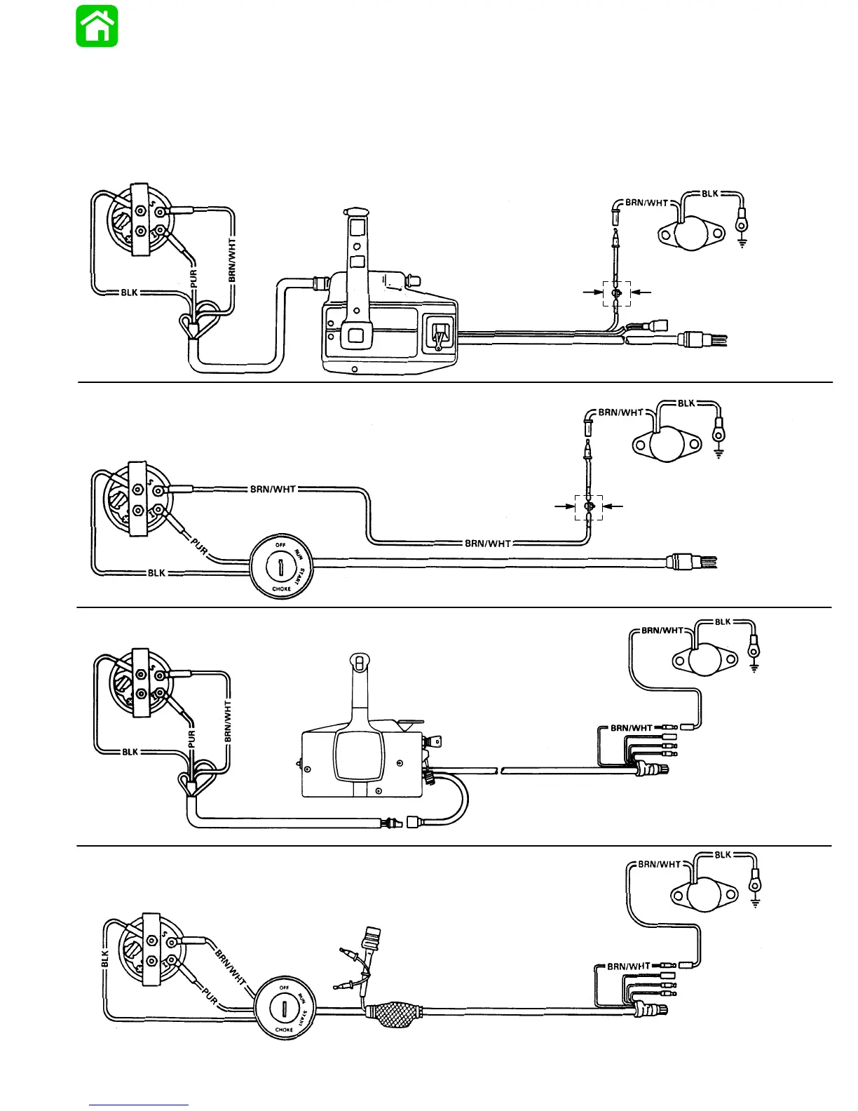
Trim Indicator Gauge and Trim Sender
Wiring Diagrams
Connect Wires Together with
Screw and Hex Nut; Apply
Liquid Neoprene to Connection
(Provided with Ignition
Switch Harness)
Wiring Diagram – For boats equipped with Quicksilver
Commander Series side mount remote control.
TRIM INDICATOR GAUGE
8 PIN HARNESS
REMOTE CONTROL
Rubber Sleeve
(Slide over
Connection)
TRIM SENDER
ENGINE
GROUND
TO ENGINE
Connect Wires Together with
Screw and Hex Nut; Apply
Liquid Neoprene to Connection
TRIM INDICATOR GAUGE
8 PIN HARNESS
BLK
TRIM SENDER
IGNITION/CHOKE
SWITCH
Wiring Diagram – For boats equipped with Quicksilver
Ignition/Choke and Main Harness Assembly.
ENGINE
GROUND
Wiring Diagram – For boats equipped with Quicksilver
Commander 2000 Series side mount remote control.
TRIM INDICATOR GAUGE
12 PIN HARNESS
REMOTE CONTROL
ENGINE
GROUND
TRIM
SENDER
TO ENGINE
TRIM INDICATOR GAUGE
IGNITION/CHOKE
SWITCH
POWER TRIM HARNESS
ENGINE
GROUND
TRIM
SENDER
TO ENGINE
22908
Rubber Sleeve
(Slide over
Connection)
TO ENGINE
Wiring Diagram – For boats equipped with Quicksilver
Ignition/Choke and Main Harness Assembly
12 PIN HARNESS