90-13645--2 1095
5A-27
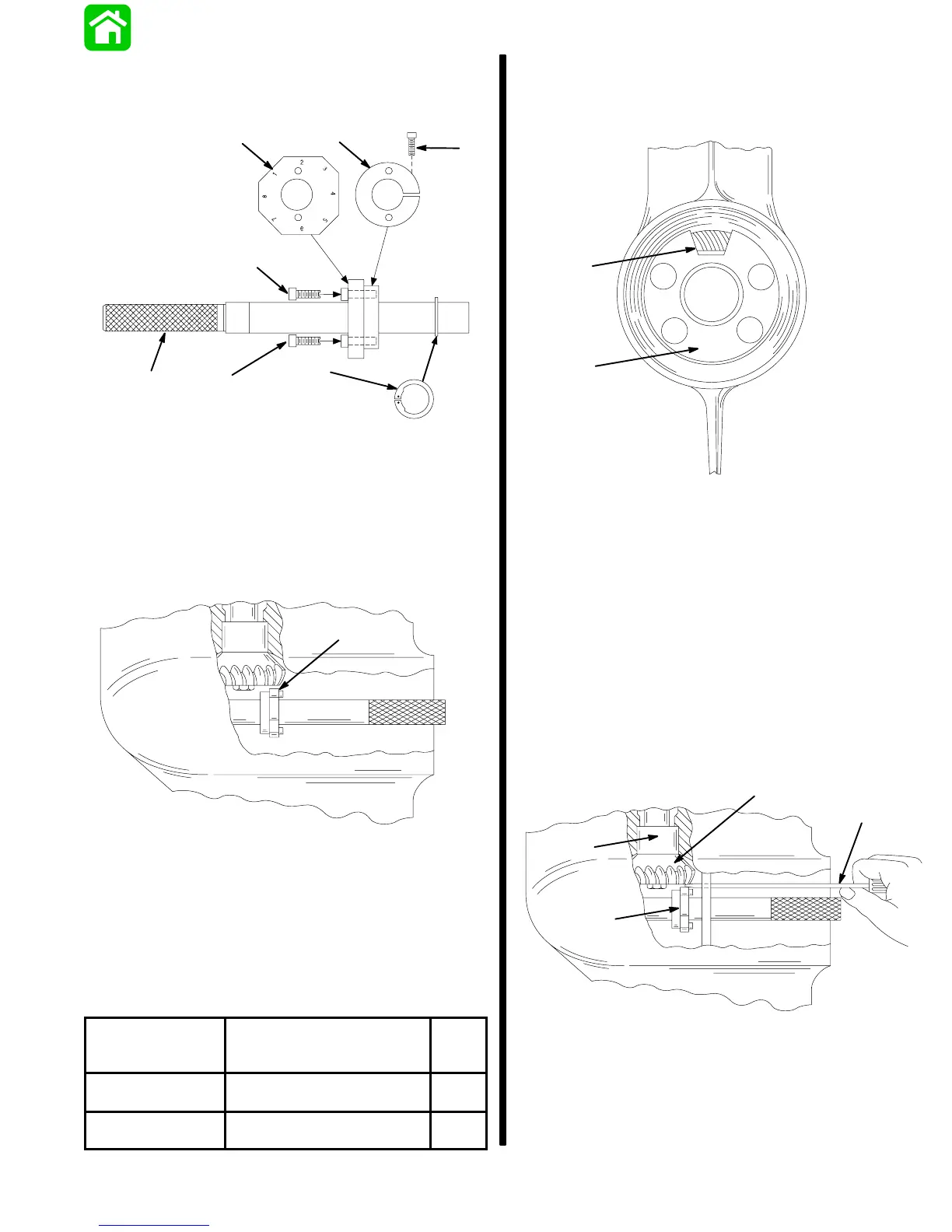
LOWER UNIT
6. Assembly Pinion Gear Locating Tool (91-12349A2)
as shown; do not tighten collar retaining bolt at
this time.
a
b
c
e
f
c
d
a - Arbor
b - Gauging Block; Install With Numbers Away From Split Collar
c - Bolt; Gauging Block Retaining
d - Split Collar
e - Bolt; Collar Retaining
f - Snap Ring
7. Insert tool into forward gear assembly; position
gauging block under pinion gear as shown.
22067
a
a - Gauging Block
8. Remove tool, taking care not to change gauging
block position, and tighten collar retaining bolt.
9. Insert tool into forward gear assembly; position
proper numbered flat (from chart) of gauging
block – under pinion gear.
MODEL
GEAR RATIO
(PINION GEAR TEETH/
REVERSE GEAR TEETH)
USE
FLAT
NO.
75-thru-90
(3 Cylinder)
13/30 8
100/115/125
(4 Cylinder)
14/29 2
10. Install the number “3” locating disc against bear-
ing carrier shoulder in gear housing.
11. Position access hole as shown.
24643
a
b
a - Locating Disc
b - Access Hole
12. Determine pinion gear depth by inserting a feeler
gauge thru access hole in locating disc.
13. The correct clearance between gauging block
and pinion gear is 0.025 (0.64mm).
14. If clearance is correct, leave Bearing Preload Tool
on drive shaft and proceed to “Determining For-
ward Gear Backlash,” following.
15. If clearance is incorrect, add (or subtract) shims
from above bearing race to lower (or raise) pinion
gear. When reinstalling pinion nut, apply Loctite
271 on threads of nut.
24643
a
b
c
d
a - Feeler Gauge
b - Gauging Block
c - Pinion Gear
d - Bearing Race