Moog Animatics SmartMotor™ Developer's Guide,Rev. L
Page 141 of 909
Encoder Source Counts into TMP
MFMUL/MFDIV
Ratio
Area A
(ascend)
MFA(200,0)
Area S
(slew)
MFSLEW(200,0)
Area D
(descend)
MFD(400,0)
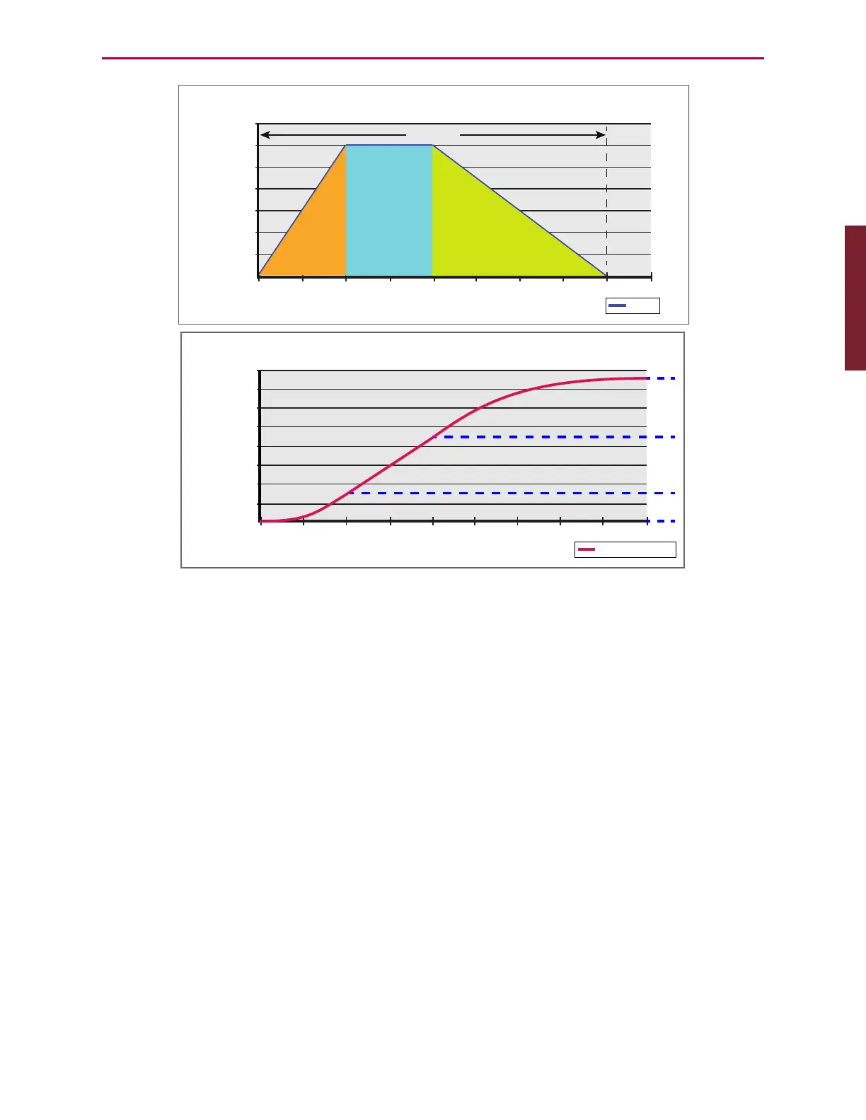
Trapezoidal Move Prole (TMP): MFMUL=300, MFDIV=100
0 100 200 300 400 500 600 700 800 900
0
0.5
1
1.5
2
2.5
3
3.5
Ratio
Ramp
Ramp up
Ramp down
Encoder Source Counts into TMP
Intermediate Counts
to Output
TMP Output Position
0 100 200 300 400 500 600 700 800 900
0
200
400
600
800
1000
1200
1400
Output position
1600
600
600
300
Ascend (Ramp up)
Slew
Descend (Ramp down)
Trapezoidal Move Profile (TMP)and Output Position Diagrams
In the first graph, the 'master' (encoder source counts into TMP) is along the horizontal axis of
the graph, and the gear ratio (MFMUL/MFDIV) is along the vertical axis of the graph. This
demonstrates that "area under the curve" is the 'slave' position.
The second graphs shows the slave position as a function of master encoder source counts to
intermediate counts (the TMP output). In this example, MFA, MFD and MFSLEW are
commanded in master units (source counts). These three commands can accept either master
(source counts) or slave units (intermediate counts) according to the second argument as a 0
or 1, respectively. The firmware automatically calculates the move accordingly. The following
example uses the command(x,0) form to specify 'master' or source counts.
MFMUL=300
MFDIV=100
MFA(200,0) 'Move 200 master counts over ascend (area "A")
MFD(400,0) 'Move 400 master counts over descend (area "D")
MFSLEW(200,0) 'Maintain sync ratio for 200 master counts (area "S")
MFR 'Calculate ratio, set mode
G
Each time a G (Go) is received, the motor follows the Trapezoidal Move Profile (TMP).
Part 1: Programming: Follow Incoming Encoder Signal With Ramps Example