Spitfire – Maintenance Manual
101
AP-74096, Rev. 1.0, 09/06/05
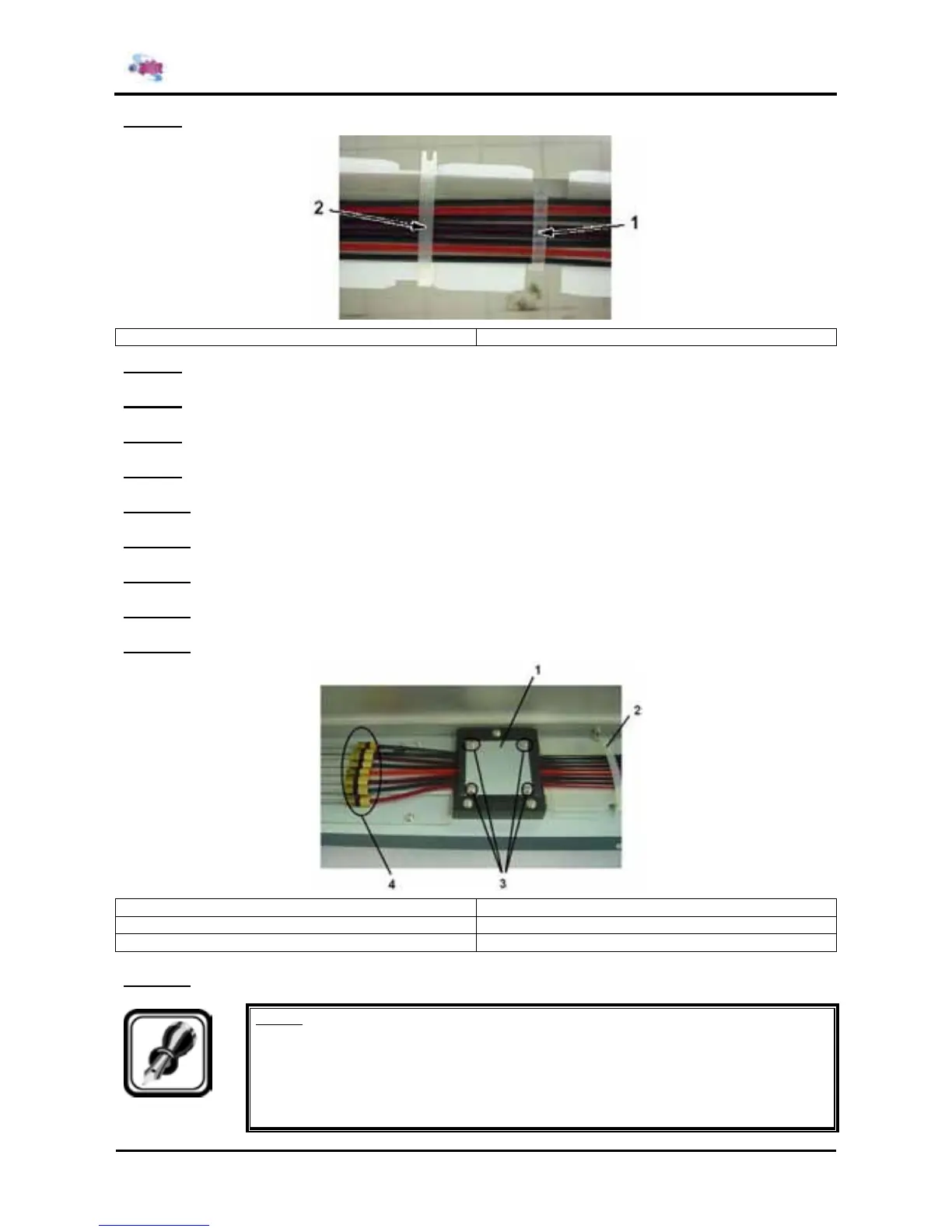
Step 5 : Completely remove tube bundles 1 and 2.
1 = Tube bundle 2 = Tube bundle 2
Step 6 : Remove the 4 screws fixing the tube clamp.
Step 7 : Remove the tube clamp.
Step 8 : Remove the coupling screws, O-ring and ink tube from the coupling.
Step 9 : Replace the ink tube.
Step 10 : Remove the 2 screws fixing the cable clamp.
Step 11 : Replace the steel bearing.
Step 12 : Replace the tube guide.
Step 13 : Remove the pipe clamp.
Step 14 : Replace the CR tape power cable.
1 = Tube push plate 2 = Cable clamp
2 = Pipe clamp 3 = Coupling, O-ring, coupling screws
4 = Screws fixing tube push plate (M3x8) 4 = Screws fixing tube cramp (M3x20)
Step 15 : Reinstall all parts in the opposite order of the removal procedure.
Notes :
¾ The CR tape power cables must be bundled during installation so that they can not
move.
¾ The edge of the tube push plate must be upside when installed.
¾ You should soak the O-ring in cleaning liquid once gain before installing it.