Spitfire – Maintenance Manual
112
AP-74096, Rev. 1.0, 09/06/05
4.7.7. Replacing the CR cursor assembly
Notes :
¾ Remove following covers before replacing the CR cursor assembly.
Side cover R: refer to "Removing side cover R"
Side cover L: refer to "Removing side cover L"
Front cover: refer to "Removing the front cover"
Y rail cover: refer to "Removing the Y rail cover"
Head cover: refer to "Removing the head cover"
Step 1 : Follow the instructions in "Replacing the cutter holder, cutter spring, cutter cap, solenoid
assembly, and solenoid spring" to "Replacing the P_EDGE sensor assembly " to remove the
parts in cursor components.
Step 2 : Slide the CR cursor assembly to the opposite side of the home position.
Step 3 : Follow the instructions in "Replacing the steel belt" to remove the steel belt from the CR cursor.
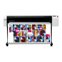
Step 4 : Remove the 4 screws fixing the CR board installation board.
Step 5 : Remove the CR board installation board.
1 = CR board installation board 2 = Screws (M3x8) fixing the CR board installation board
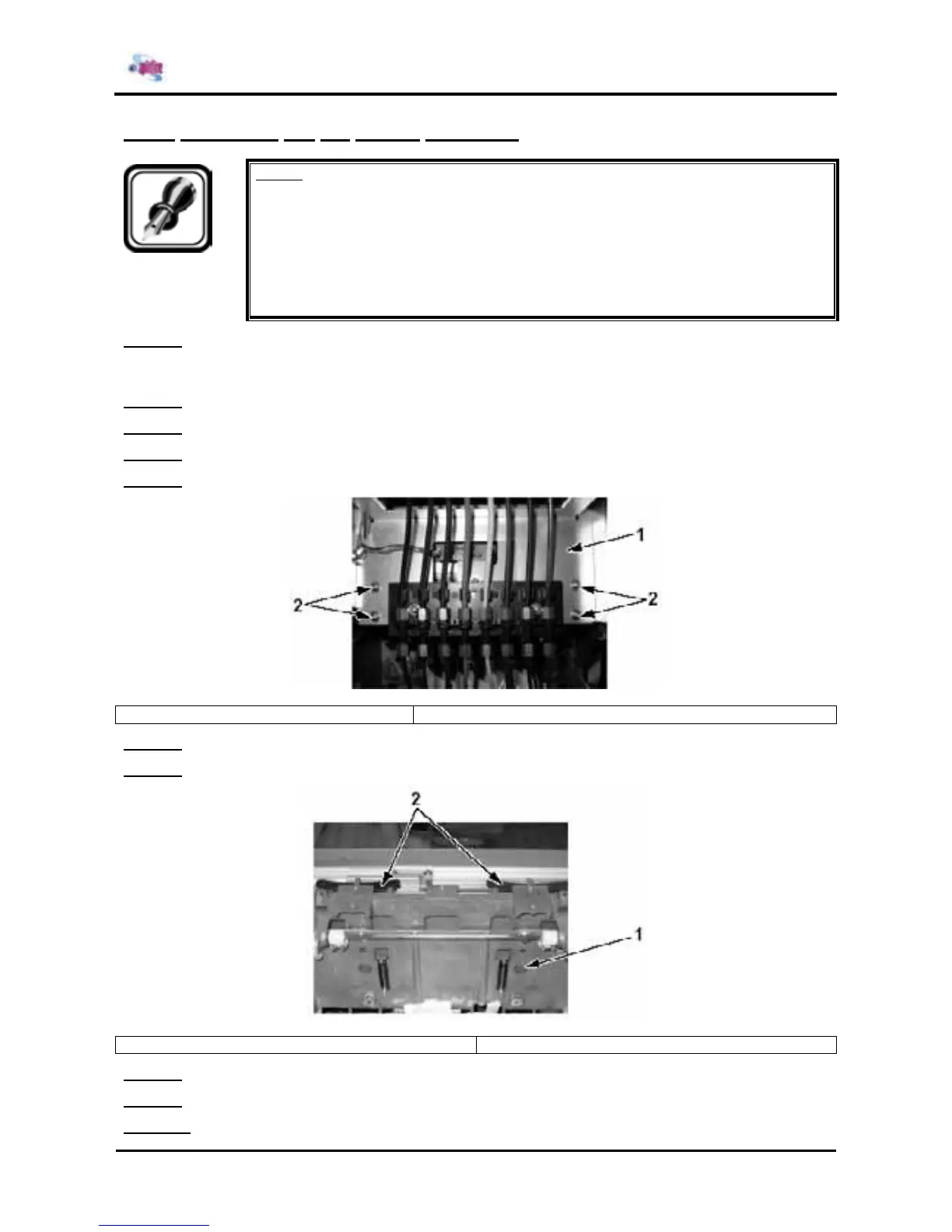
Step 6 : Remove the T fence.
Step 7 : Remove the CR blade spring.
1 = CR cursor assembly 2 = CR blade spring
Step 8 : Replace CR cursor assembly.
Step 9 : Reinstall all parts in the opposite order of the removal procedure.
Step 10 : Perform head height adjustment according to "Head height adjustment".