Spitfire – Maintenance Manual
74
AP-74096, Rev. 1.0, 09/06/05
4.4.3. Replacing the inlet assembly, inlet board assembly and lever foot
SW
cable assembly
Step 1 : Follow the instructions in "Replacing the Mainboard assembly, HDD_Extension board assembly,
HEAD_DRV board assembly, PCI_Linux board assembly and cooling fan assembly" to remove
the Mainboard assembly.
Step 2 : Follow step 2 to 4 in "Replacing the power source board assembly" to remove the Mainboard
assembly.
Step 3 : Remove the connector between the inlet board assembly and the inlet assembly.
Step 4 : Remove the 4 screws fixing the inlet board assembly.
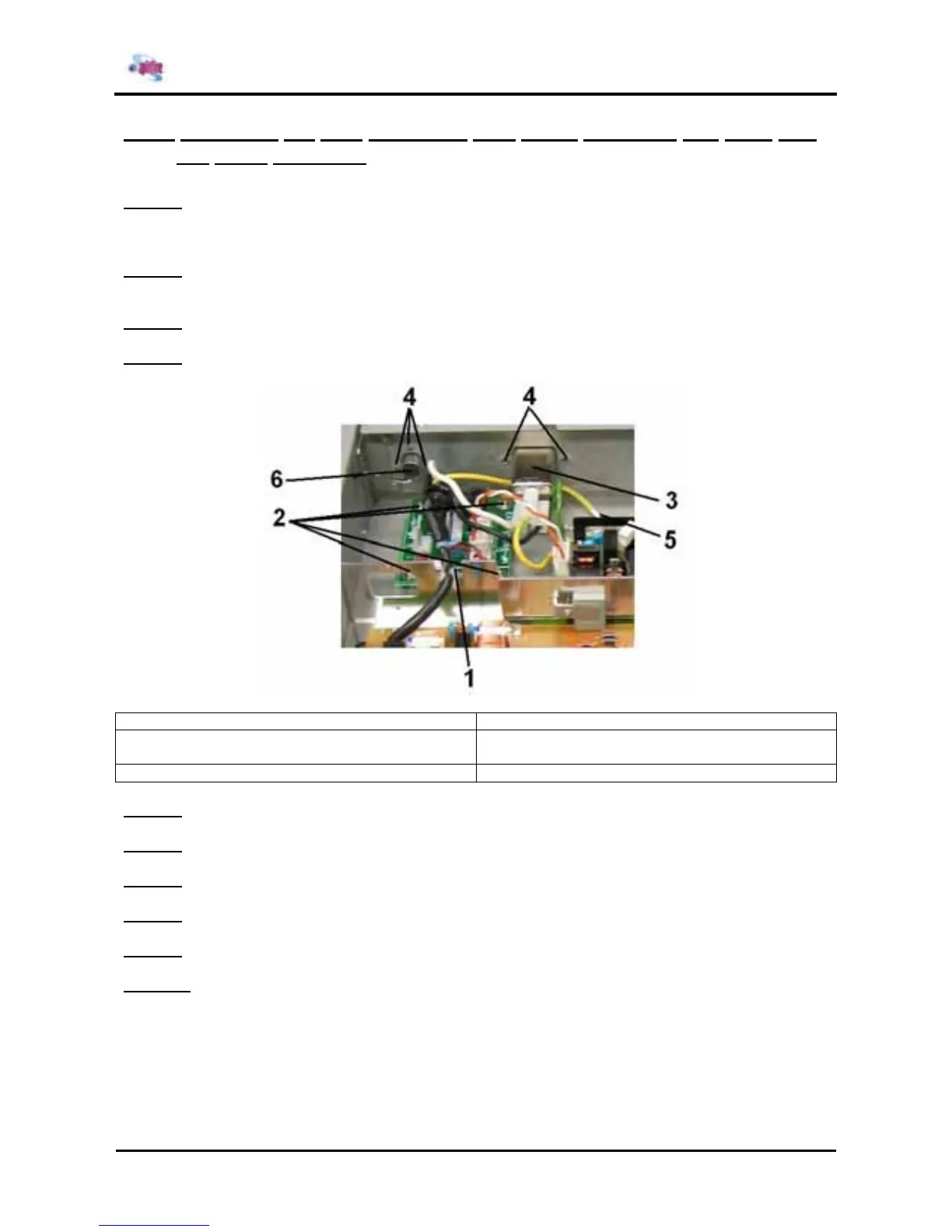
1 = Inlet board assembly 2 = Screws (M3x6) fixing the inlet board assembly
3 = Inlet assembly 4 = Screws (M3x6) fixing the inlet assembly and
lever foot SW cable assembly
5 = Screw (M4x8) fixing the inlet assembly 6 = Lever foot SW cable assembly
Step 5 : Replace the inlet board assembly.
Step 6 : Remove the 3 screws fixing the inlet assembly.
Step 7 : Replace the inlet assembly.
Step 8 : Remove the 3 screws fixing the lever foot SW cable assembly.
Step 9 : Replace the lever foot SW cable assembly.
Step 10 : Reinstall all parts in the opposite order of the removal procedure.