Spitfire – Maintenance Manual
73
AP-74096, Rev. 1.0, 09/06/05
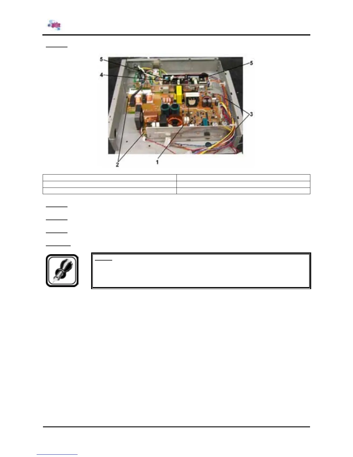
Step 6 : Remove the 4 screws fixing the power source.
1 = Power source board assembly 2 = Screws (M4x8) fixing the power board assembly
3 = Hexagon nut fixing the power board assembly 4 = Power source
5 = Screws (M3x6) fixing the power source
Step 7 : Replace the power source.
Step 8 : Remove the 2 screws and 2 hexagon nuts fixing the power source board assembly.
Step 9 : Remove the power source board assembly.
Step 10 : Reinstall all parts in the opposite order of the removal procedure.
Notes :
¾ When installing the mainboard assembly, be careful not to pinch the foot SW cables
by the mainboard base.