Spitfire – Maintenance Manual
54
AP-74096, Rev. 1.0, 09/06/05
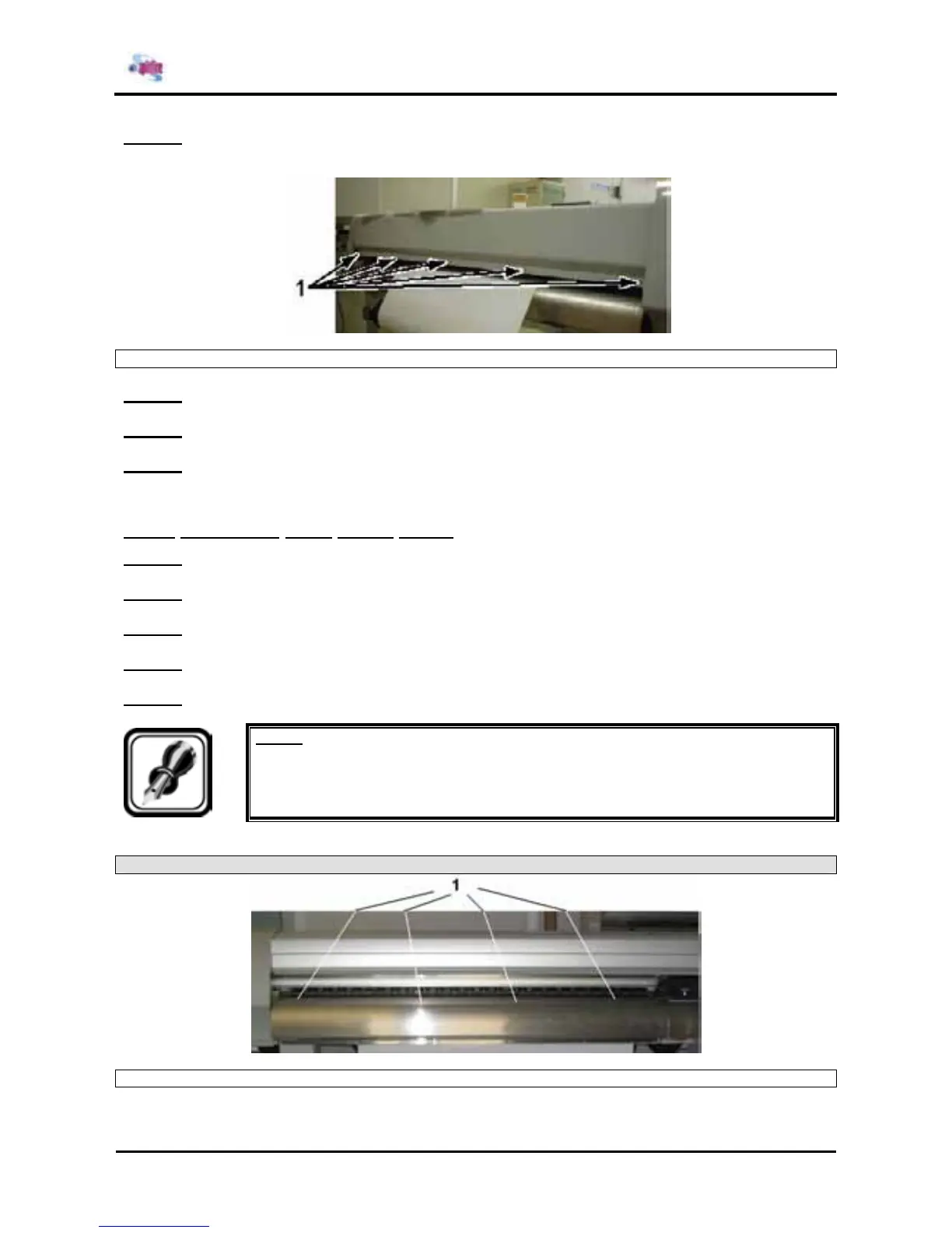
Step 6 : Remove the 5 screws from the rear of the Y rail cover.
¾ If the machine is an 90-inch model, there are 8 screws on the rear Y rail cover.
1 = Screws (M4x8) on the rear of the Y rail cover
Step 7 : Remove the Y rail cover.
Step 8 : Replace the parts inside the printer.
Step 9 : Reinstall all parts in the opposite order of the removal procedure.
4.2.7. Removing front paper guide
Step 1 : Remove side cover L.
Step 2 : Remove side cover R.
Step 3 : Remove the front cover.
Step 4 : Remove the Y rail cover.
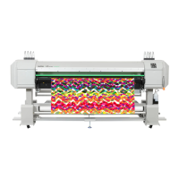
Step 5 : Remove the screws from the top of front media guide.
Notes :
¾ Please note that the amount of screws is size dependent.
Spitfire
1 = Screws on the top of front media guide