Spitfire – Maintenance Manual
57
AP-74096, Rev. 1.0, 09/06/05
4.2.9. Removing the head cover
Step 1 : Remove the I/H cover.
Step 2 : Remove side cover R.
Step 3 : Remove side cover L.
Step 4 : Remove the front cover.
Step 5 : Remove the Y rail cover.
Step 6 : Unlock the head.
Notes :
¾ Please refer to the ‘Head lock menu’.
Step 8 : Pull the head out to the left of the maintenance station.
Caution :
When pulling the head out, do not press on the cutter cap. Doing so could damage the
cutter blade.
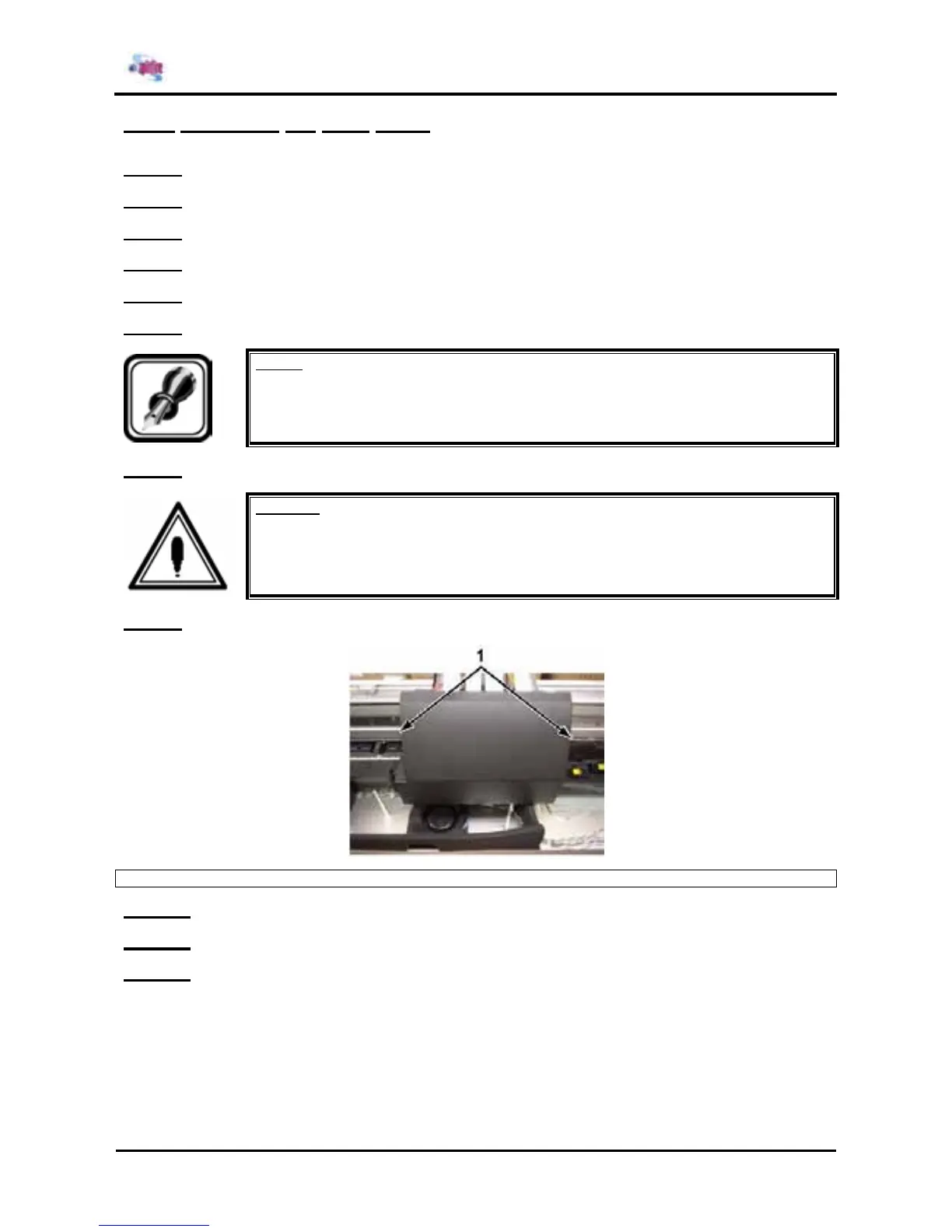
Step 9 : Remove the 2 screws fixing the head cover.
1 = Screws (M3x8) fixing the head cover
Step 10 : Remove the head cover.
Step 11 : Replace the parts inside the printer.
Step 12 : Reinstall all parts in the opposite order of the removal procedure.