Spitfire – Maintenance Manual
72
AP-74096, Rev. 1.0, 09/06/05
4.4.2. Replacing the power source board assembly
Caution :
When removing the power source board assembly, remove the power cable and set it
aside for at least 5 minutes in order to completely discharge the electric charge
remaining in the electrolytic capacitor before continuing with the procedure.
Touching the substrate before discharging the capacitor causes electric shock.
Step 1 : Follow the instructions in "Replacing the Mainboard assembly, HDD_Extension board assembly,
HEAD_DRV board assembly, PCI_Linux board assembly and cooling fan assembly" to remove
the Mainboard assembly.
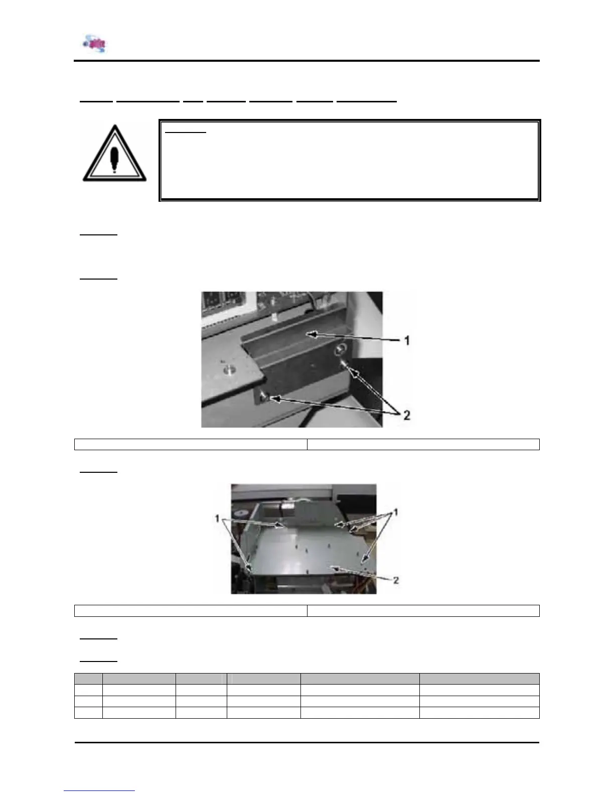
Step 2 : Remove the 2 screws fixing the PS board cover.
1 = PS board cover 2 = Screws (M3x6) fixing the PS board cover
Step 3 : Remove the 5 screws fixing the Mainboard base.
1 = Screws (M3x8) fixing the Mainboard base 2 = Mainboard base
Step 4 : Remove the Mainboard base.
Step 5 : Remove the following connectors from the power source board assembly.
N° Connector N° # of pins Colour Connected to Remarks
1 CN2 3 White Mainboard J101
2 CN3 4 White + 5V adhesion FAN Output four adhesion FAN
3 CN4 12 White Mainboard J101