Spitfire – Maintenance Manual
95
AP-74096, Rev. 1.0, 09/06/05
4.6.3. Replacing the SLIDE motor assembly, HD_SLIDE sensor
assembly,
and slide motor installation board
Caution :
The motor is hot after the product has been operated, so be careful not to burn yourself.
Notes :
¾ Remove following covers before replacing the SLIDE motor assembly, HD_SLIDE
sensor assembly, and slide motor installation board.
Side cover R: refer to "Removing side cover R"
Side cover L: refer to "Removing side cover L"
Front cover: refer to "Removing the front cover"
Y rail cover: refer to "Removing the Y rail cover"
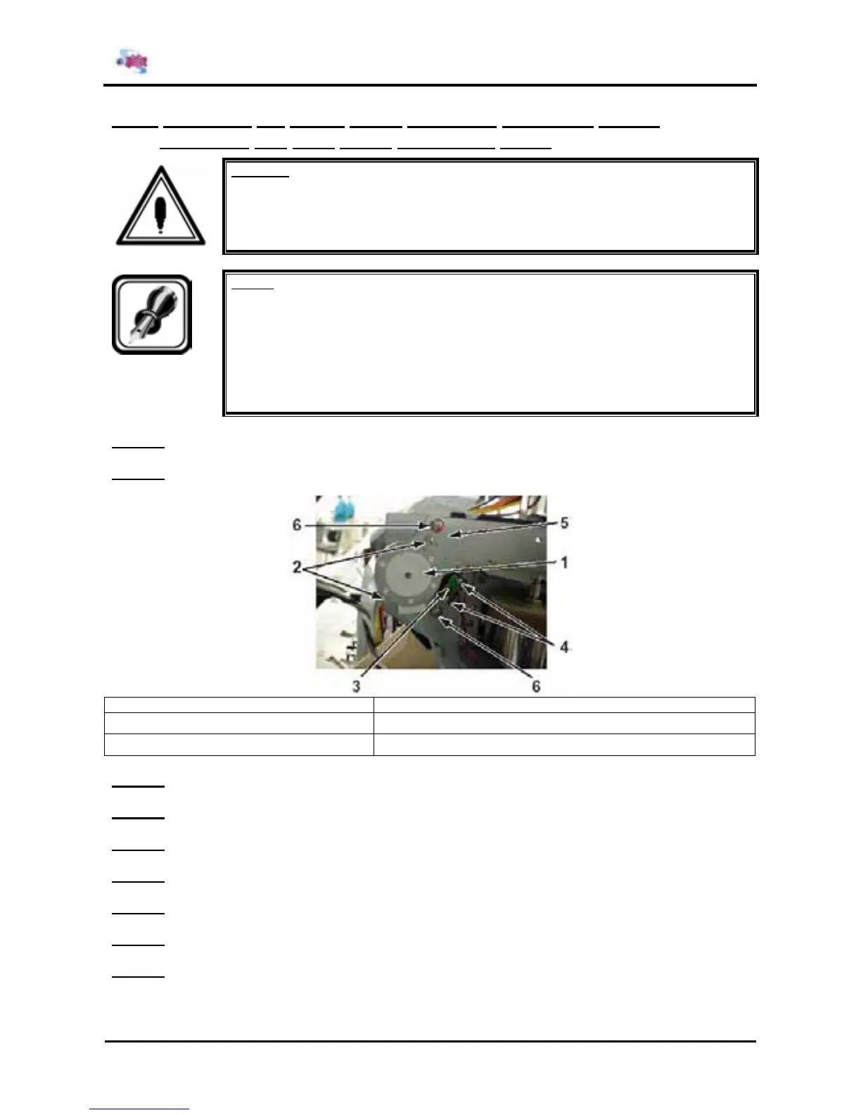
Step 1 : Remove the connectors on the SLIDE motor assembly and HD_SLIDE sensor assembly.
Step 2 : Remove the 2 screws fixing the SLIDE motor assembly.
1 = SLIDE motor assembly 2 = Screws (M3x6) fixing the SLIDE motor assembly
3 = HD_SLIDE sensor assembly 4 = Screws (M2x8) fixing the HD_SLIDE sensor assembly
5 = Slide motor installation board 6 = Screws (M4x6) fixing the slide motor installation board
Step 3 : Replace the SLIDE motor assembly.
Step 4 : Remove the 2 screws fixing the HD_SLIDE sensor assembly.
Step 5 : Replace the HD_SLIDE sensor assembly.
Step 6 : Remove the 2 screws fixing the slide motor installation board.
Step 7 : Replace the slide motor installation board.
Step 8 : Reinstall all parts in the opposite order of the removal procedure.
Step 9 : Make sure that the Idler moves smoothly.