Spitfire – Maintenance Manual
108
AP-74096, Rev. 1.0, 09/06/05
Step 7 : Remove the H ink tube, coupling screw and O-ring from the damper assembly.
Step 8 : Replace the damper assembly.
Step 9 : Replace the H ink tube and O-ring.
Notes :
¾ Please soak the O-ring in cleaning liquid before installation.
Step 10 : Reinstall all parts in the opposite order of the removal procedure.
Notes :
¾ When tightening coupling screws, finger-tighten those. If using tools, it may result
in cracking where the screws fix damper and fail to fill the ink.
¾ Do not grasp the film area of the damper strongly. Doing so may cause faulty
damper and print failure.
4.7.4. Replacing the CR board assembly
Notes :
¾ To replace the board and connect or disconnect the FFC type cable, you should
leave the plug disconnected from the power socket for a while. Otherwise, over-
current could be generated and damage the board
¾ Remove following covers before replacing the CR board assembly.
Side cover R: refer to "Removing side cover R"
Side cover L: refer to "Removing side cover L"
Front cover: refer to "Removing the front cover"
Y rail cover: refer to "Removing the Y rail cover"
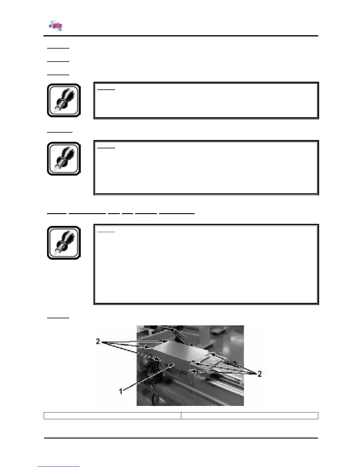
Step 1 : Remove the 8 screws fixing the CR cover.
1 = CR cover 2 = Screws (M3x8) fixing the CR cover