Spitfire – Maintenance Manual
118
AP-74096, Rev. 1.0, 09/06/05
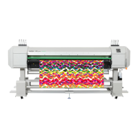
Step 14 : Use the build-in mirror (in the left maintenance cover) to check that the cap does not
impinge on the nozzle.
1 = Print head (nozzle face) 2 = Nozzle
3 = Cap trace 4 = Mirror
Step 15 : Reinstall the rest of the parts in the opposite order of the removal procedure. Make sure
that both cam and gears in the capping station assy are sufficient applied with grease
(KY-80050)
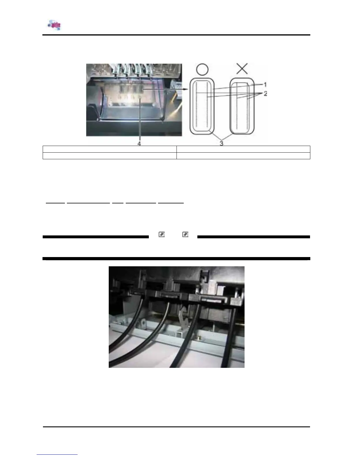
4.8.1. Assembling the Capping Station
Step 1 : Hook the lever of the plastic subassy with the head caps to the hook on the basic plate.
There’s one lever and one hook on the basic plate.
Notes
Turn the wheel on the basic plate until the hook is a little in the up position.