Spitfire – Maintenance Manual
26
AP-74096, Rev. 1.0, 09/06/05
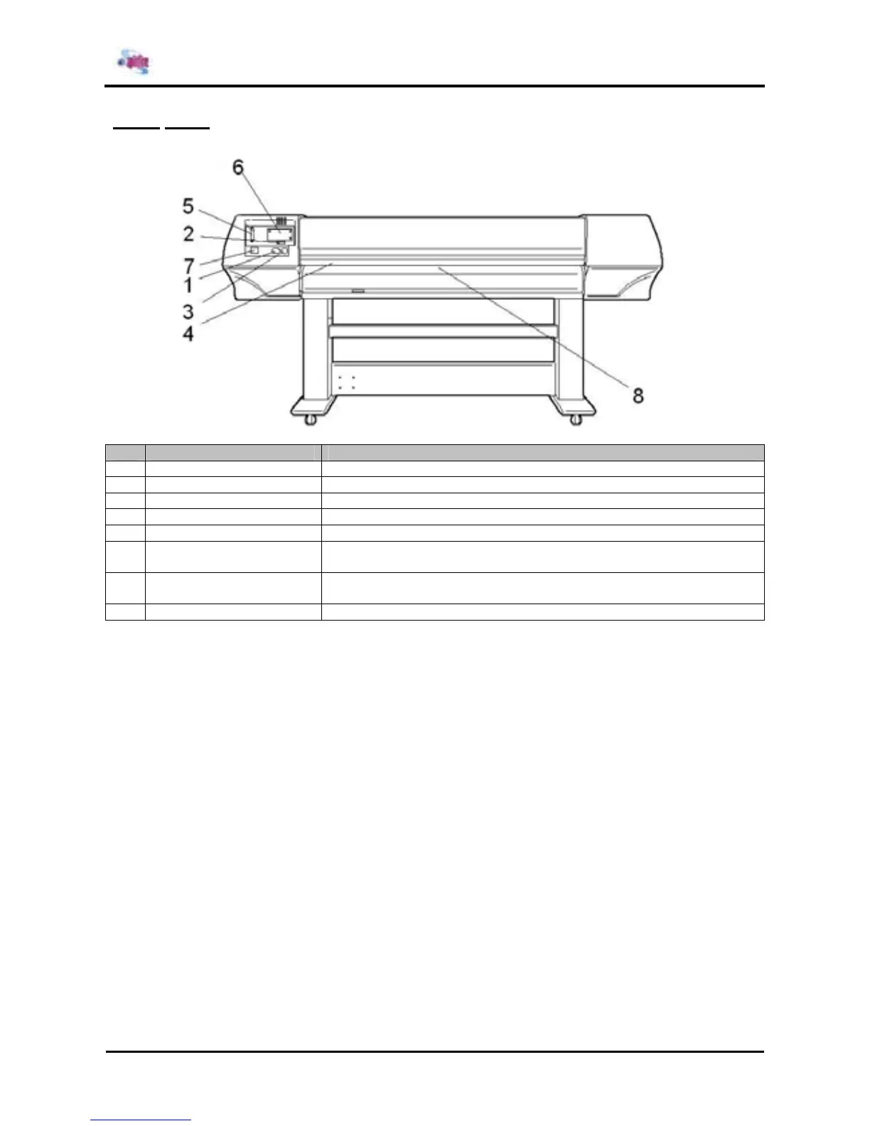
2.3.2. Back
No. Name Function
1 AC inlet This is the inlet interface to which the power plug is connected.
2 Interface connector This is the connector to which the interface cable is connected.
3 Foot switch connector This is the connector to which the foot switch cable is attached.
4 Insertion slot This is the slot for inserting media when loading it.
5 Interface slot The network interface board attaches here.
6 Hard disk slot The hard disk attaches here. When not using a hard disk, keep the
cover closed.
7 Nameplate rating The type, name, serial number, rating and other details of the printer are
labelled here.
8 Rear Heater Supports the media during printing and houses the pre-heaters.