Spitfire – Maintenance Manual
105
AP-74096, Rev. 1.0, 09/06/05
4.7.2. Replacing the print head assembly and head tape power cable
Notes :
¾ To replace the board and connect or disconnect the FFC type cable, you should
leave the plug disconnected from the power socket for a while. Otherwise, over-
current could be generated and damage board.
¾ Remove following covers before replacing the print head assembly and head tape
power cable.
Side cover R: refer to "Removing side cover R"
Side cover L: refer to "Removing side cover L"
Front cover: refer to "Removing the front cover"
Y rail cover: refer to "Removing the Y rail cover"
Head cover: refer to "Removing the head cover"
¾ The print head assembly has been pre-adjusted. Do not disassemble it.
Step 1 : Drain the ink from all ink paths according to "Head wash menu".
Step 2 : Loosen the 2 screws fixing the damper clamp.
1 = Damper clamp 2 = Screws (M3x6) fixing the damper clamp
Step 3 : Remove the damper clamp.
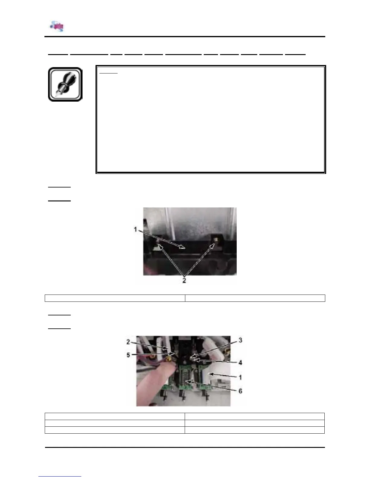
Step 4 : Remove the head tape power cable.
1 = Head tape power cable 2 = Damper assembly
3 = Head stationary plate / head spacer 4 = Step-bore screw
5 = Screws (M2.6x5) fixing the head stationary plate 6 = Print head assembly