Spitfire – Maintenance Manual
106
AP-74096, Rev. 1.0, 09/06/05
Step 5 : Remove the damper assembly from the print head assembly.
Step 6 : Remove the screw and step-bore screw fixing the head stationary plate.
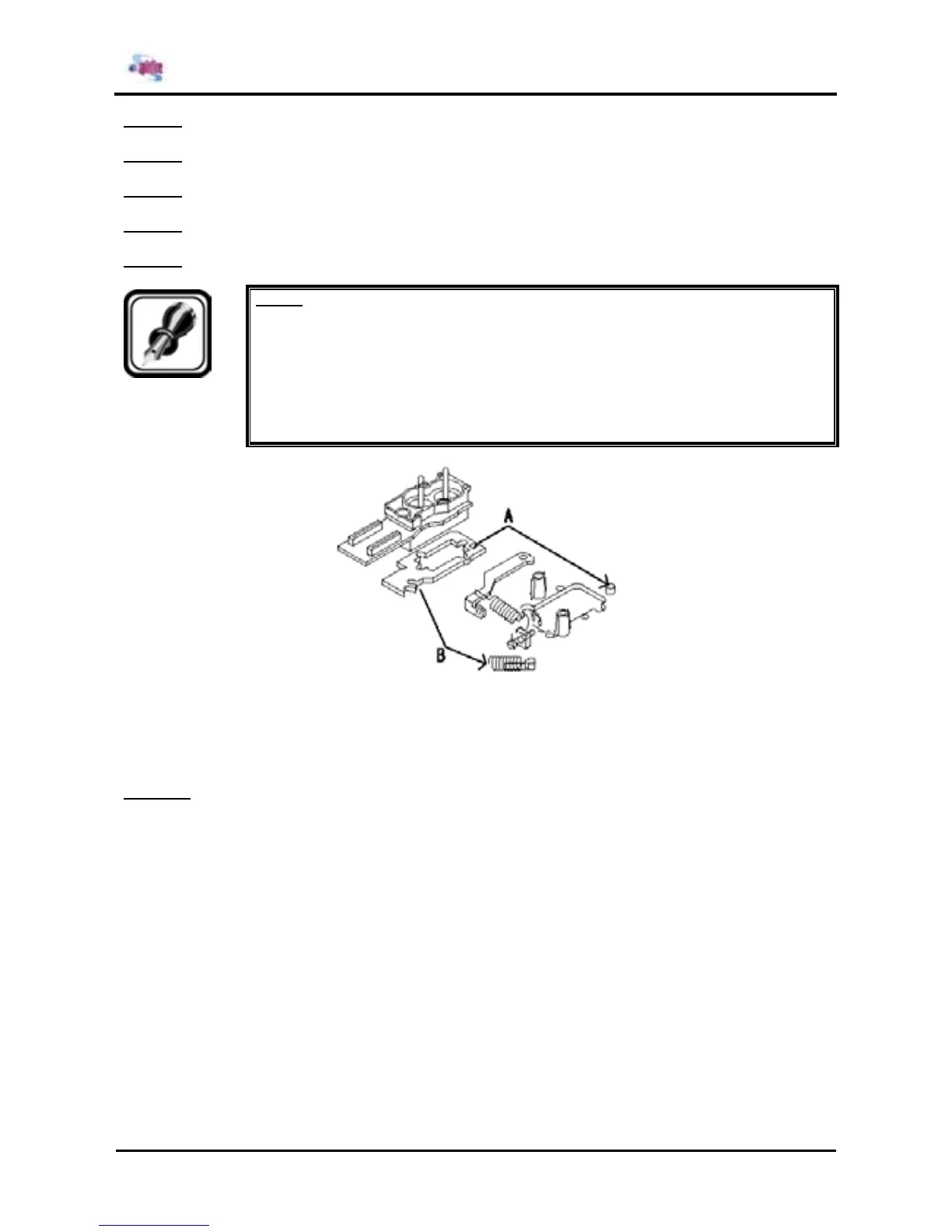
Step 7 : Remove the rotation adjustment spring under the head with small flat-head driver or another tool.
Step 8 : Replace the print head assembly.
Step 9 : Reinstall all parts in the opposite order of the removal procedure.
Notes :
¾ Place the removed damper assembly facing upward and fix with tape or place it in a
container to prevent the ink from leaking. Ink adhesion on board may cause faulty
print head.
¾ Align the head tape power cables one by one to each head and paste together with
double-faced tape.
¾ Make sure that the head does not float when installing the head.
A : Insert the concave portion of the head base in the rear of the cursor convex portion of the
cursor.
B : Insert the rotation adjustment spring into the convex portion of the head base on the right
front.
Step 10 : Perform head precision adjustment according to "Head precision adjustment".