Spitfire – Maintenance Manual
75
AP-74096, Rev. 1.0, 09/06/05
4.4.4. Replacing the JUNCTION board assembly
Notes :
¾ To replace board and connect or disconnect the FFC type cable, you should leave
the plug disconnected from the power socket for a while. Otherwise, over-current
could be generated and damage the board.
¾ Remove the following parts before replacing the JUNCTION board assembly.
I/H cover: refer to "Removing the I/H cover"
Side cover R: refer to "Removing side cover R"
Step 1 : Remove following connectors from the JUNCTION board assembly.
N° Connector N° # of pins Colour Connected to Remarks
1 J401 30 White Mainboard – J134 Lock type or Plug-in
2 J402 30 White Mainboard – J133 Lock type or Plug-in
3 J403 4 White Ink sensor K Cartridge 1
4 J404 4 Black Ink sensor C Cartridge 2
5 J405 4 Red Ink sensor M Cartridge 3
6 J406 4 Yellow Ink sensor Y Cartridge 4
7 J407 4 Blue Ink sensor LC Cartridge 5
8 J408 5 White Ink sensor LM Cartridge 6
9 J409 5 Black Ink sensor O Cartridge 7
10 J410 5 Red Ink sensor G Cartridge 8
11 J411 5 Yellow SC cable K Cartridge 1
12 J412 5 Blue SC cable C Cartridge 2
13 J413 6 White SC cable M Cartridge 3
14 J414 6 Black SC cable Y Cartridge 4
15 J415 6 Red SC cable LC Cartridge 5
16 J416 6 Yellow SC cable LM Cartridge 6
17 J417 6 Blue SC cable O Cartridge 7
18 J418 7 White SC cable G Cartridge 8
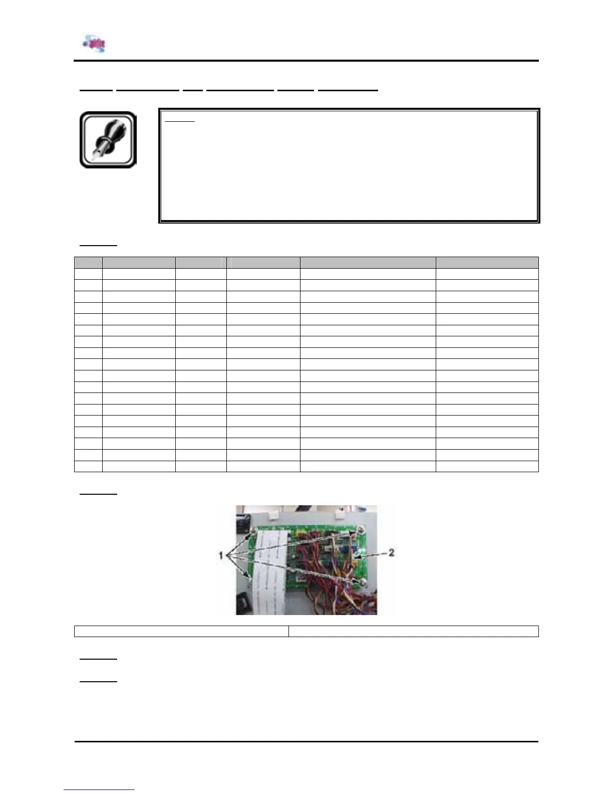
Step 2 : Remove the 4 screws fixing the JUNCTION board assembly.
1 = JUNCTION board assembly 2 = Screws (M3x6) fixing the JUNCTION board assembly
Step 3 : Replace the JUNCTION board assembly.
Step 4 : Reinstall all parts in the opposite order of the removal procedure.