Spitfire – Maintenance Manual
117
AP-74096, Rev. 1.0, 09/06/05
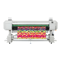
Step 9 : Remove the 6 screws fixing the maintenance assembly.
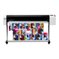
1= screws (M3x8) fixing the maintenance assembly Position of the holes
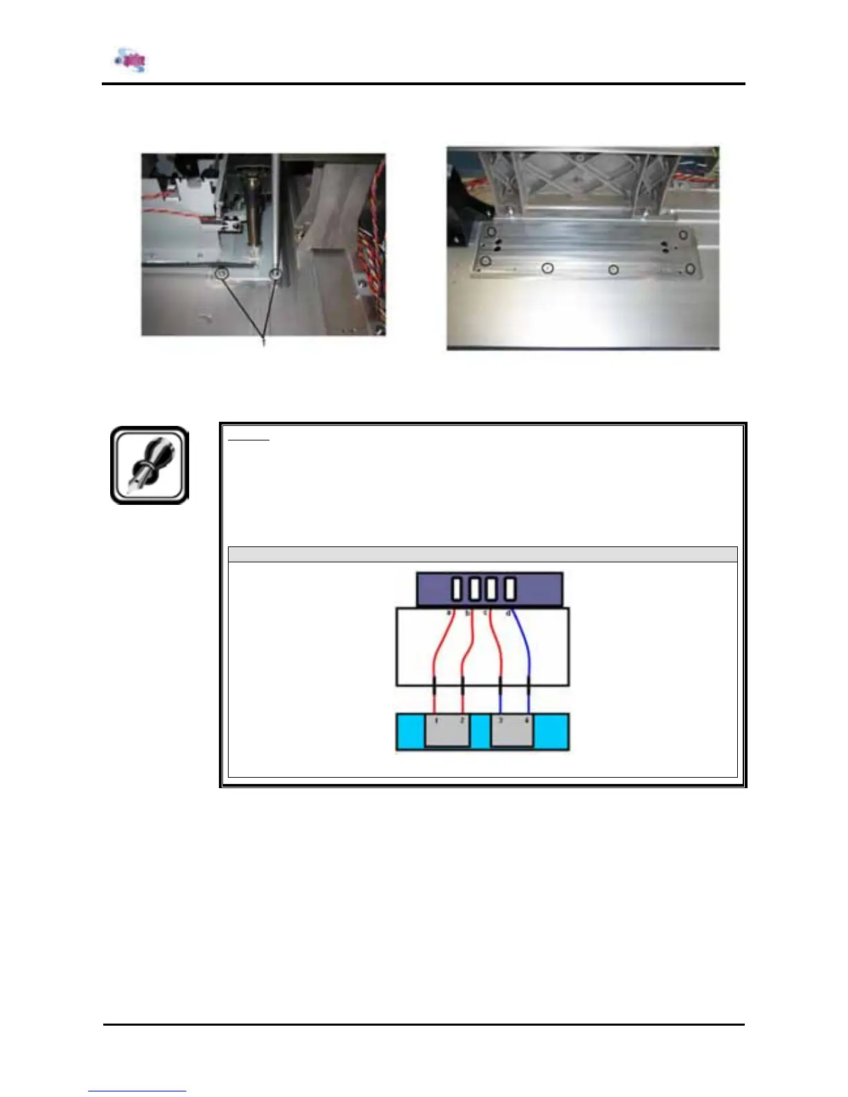
Step 10 : Replace the maintenance assembly.
Notes :
¾ Secure the maintenance assembly so that it abuts against the rear right portion.
¾ The connection sequence for the tubes is as follows: Numbers in brackets ( ) are
the cap numbers from left to right as viewed from the front of the main body.
65 and 90 Spitfire
Step 11 : Move the cursor to the opposite side of the origin.
Step 12 : Cap once.
Step 13 : Move the CR Cursor to the left side of the printer.