Spitfire – Maintenance Manual
97
AP-74096, Rev. 1.0, 09/06/05
Step 5 : Remove the T fence from the hook.
Step 6 : Pull out the T fence in the direction of the arrow as shown in the previous figure while being
careful not to damage the CR_ENC assembly.
Step 7 : Reinstall all parts in the opposite order of the removal procedure.
Notes :
¾ When installing the T fence, pay attention to the following :
When there is a protective film on the T fence, remove the film and install
the T fence.
Properly install the T fence to the hooks on the T fence stationary plate.
Refer to the figure in step 2.
The T fence and the hooks on the stationary plate must have a loose fit.
When securing the stationary plate with screws, it must be loosened
enough so the T fence can be moved.
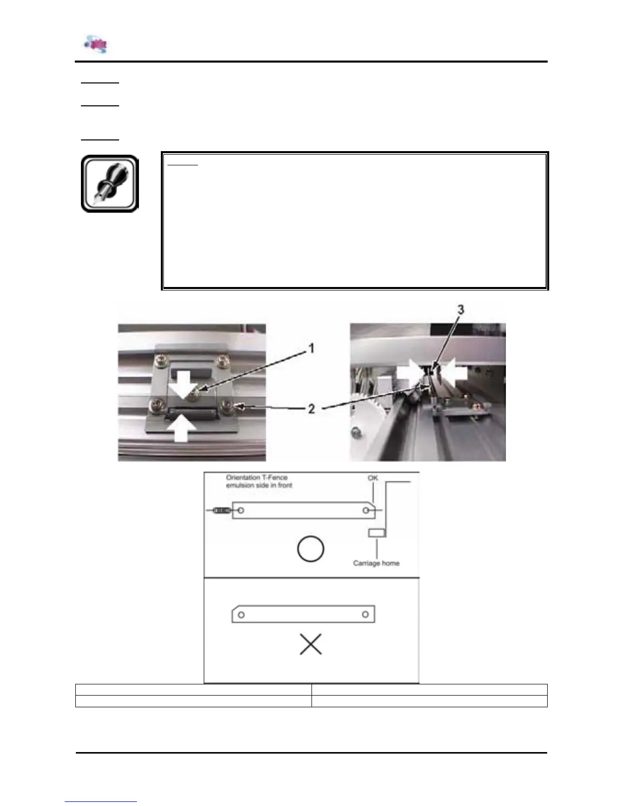
Insert the T fence into the hooks on the T fence push plate and the
CR_ENC assembly. Refer to the following figure.
1 = T fence push plate 2 = T fence
3 = CR_ENC assembly