164 5 HARD START AND NO START DIAGNOSTICS
Monitoring Engine Systems using Breakout Box
NOTE: Do this procedure, if an EST is not available.
This is an alternate method.
Tools
• Breakout Box
• Digital Multimeter (DMM)
Procedure
WARNING: To avoid serious personal injury,
possible death, or damage to the engine or
vehicle, read all safety instructions in the “Safety
Information” section of this manual.
1. See “DT 466 Performance Specifications” –
Appendix A (page 595) or “DT 570 and HT 570
Performance Specifications” – Appendix B (page
619) and Section 7 for specifications, operational
voltages, and values. Record on Diagnostic
Form.
2. Turn the ignition switch to OFF and ensure all
accessories are turned off.
3. Remove X1, X2 and X3, X4 connectors from
ECM.
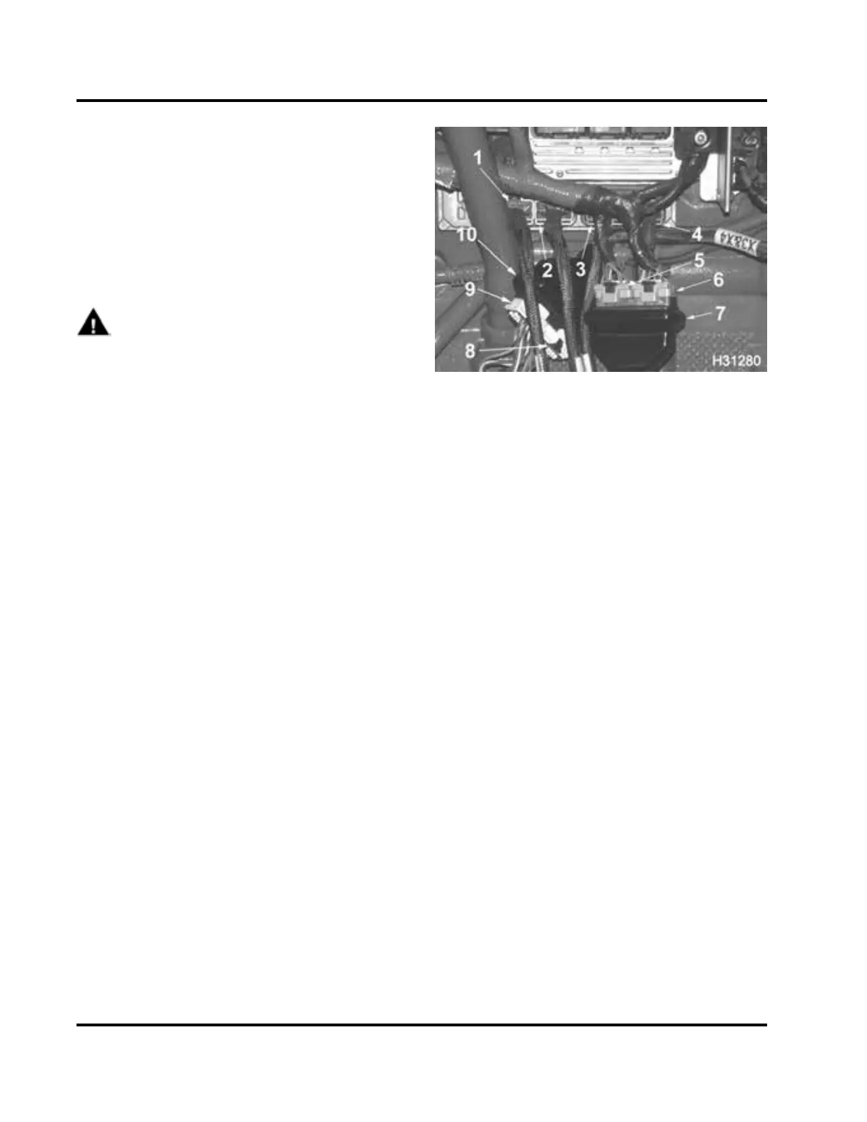
Figure 189 Engine and chassis breakout box
connections
1. Breakou t box connector X4 to ECM
2. Breakou t box connector X3 to ECM
3. Breakou t box connector X2 to ECM
4. Breakou t box connector X1 to ECM
5. Engine wiring harness ECM connector X2 to
breakout box header
6. Engine wiring harness ECM connector X1 to
breakout box header
7. Breakou t box header X1 and X2 engine to breakout
box
8. Chassi s wiring harness con nector to breakout box
header
9. Chassi s wiring harness con nector to breakout box
header
10. Breakout bo x he ader X3 and X4 breakout box to
chassis
4. Connect breakout box connectors X1, X2 and X3,
X4 to ECM.
5. Connect wiring harness connectors to breakout
box headers X1, X2 and X3, X4.
EGES-270-1
Read all safety instructions in the "Safety Information" section of this manual before doing any proced ures.
Follow all warnings, cautions, and notes.
©August 2008 Navistar, Inc.
 Loading...


