570 8 DIAGNOSTIC TOOLS AND ACCESSORIES
Electronic Circuit Testing
Electrical Theory
Voltage
Voltage is electrical pressure o r force that pushes
current through a circuit. The pressure is measured
in volts. The symbol V (for example, 12 V) is used
in circuit diagrams to denote voltage. The letter E
(Electromotive force) is also used for voltage. Voltage
can be compared to the pressure necessary to push
water through a metering valve.
Low voltage to a lamp will cause the lamp to glow
dimly. This can be caused by low source voltage
(discharged battery or low alternator output) or
by high circuit resistanc e res ulting from a poor
connection. Resistance from a poor connection or
poor ground is an additional load in the circuit. The
additional load reduces voltage available to push
current through the load device. Before making any
meter measurements, review Ohm’s Law.
Ohm’s Law
Ohm’s Law describes the relationship between
current, vo ltage, and re sistance in an electric al
circuit. Ohm’s Law also provides the basic formula
for calculations.
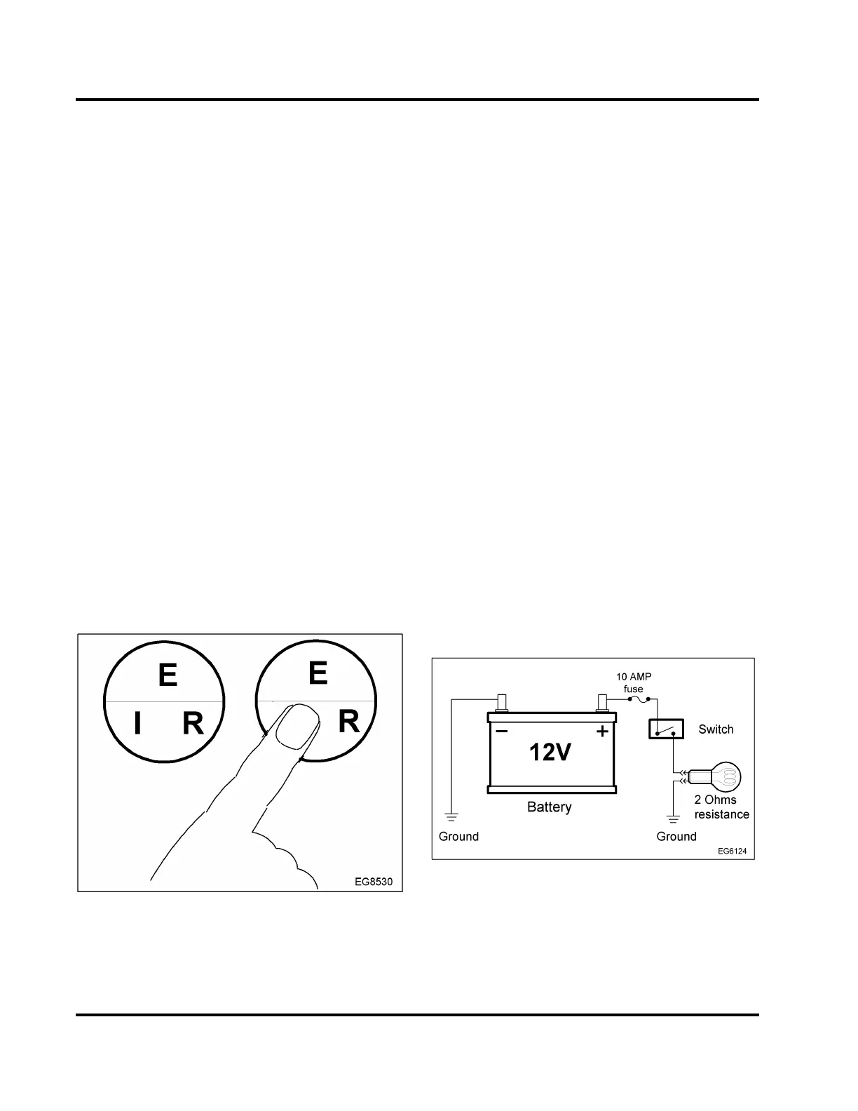
Figure 549 Ohm’s Law
Memorize the formula in the circle. Cover the letter
with a finger for the desired formula. For example, I is
covered, the formula is I = E ÷ R.
If two values are known for a given circuit, the
missing one can be found by substituting the values
in amperes, volts, or ohms.
The three basic formulas for Ohm’s Law are as
follows:
I = Current (amperes)
E = Voltage (volts)
R = Resistance (ohms)
•I=E÷R
This formula states that the current flow (I) in
the circuit equals the voltage (E) applied to the
circuit divid ed by the total resistance (R) in the
circuit. This shows that an increase in v oltag e or
a decrease in resistance increases the current
flow.
• E=I×R
This formula states that t he voltage (E) applied to
the circuit equals the current flow (I) in the circuit
multiplied by the tota l resistance (R) in th e circuit.
The voltage drop is caused by resistance across a
particular load device in a series of load devices.
•R=E÷l
This formula states that the total resistance (R)
in the circuit equals the voltage (E) applied to the
circuit divided by the current flow (I) in the circuit.
Resistance can be calculated for a specific current
flow when a specific voltage is applied.
Figure 550 Simple electrical circuit
In a typical circuit, battery voltage is applied to a bulb
through a 10 am p fuse and a switch . C losing the
switch turns on the bulb.
To find the current flow, use the formula I = E ÷ R:
EGES-270-1
Read all safety instructions in the "Safety Information" section of this manual before doing any procedures.
Follow all warnings, cautions, and notes.
© August 2008 Navistar, Inc.
 Loading...


