7 ELECTRONIC CONTROL SYSTEMS DIAGNOSTICS 547
VSS Pin-Point Diagnostics (Manual
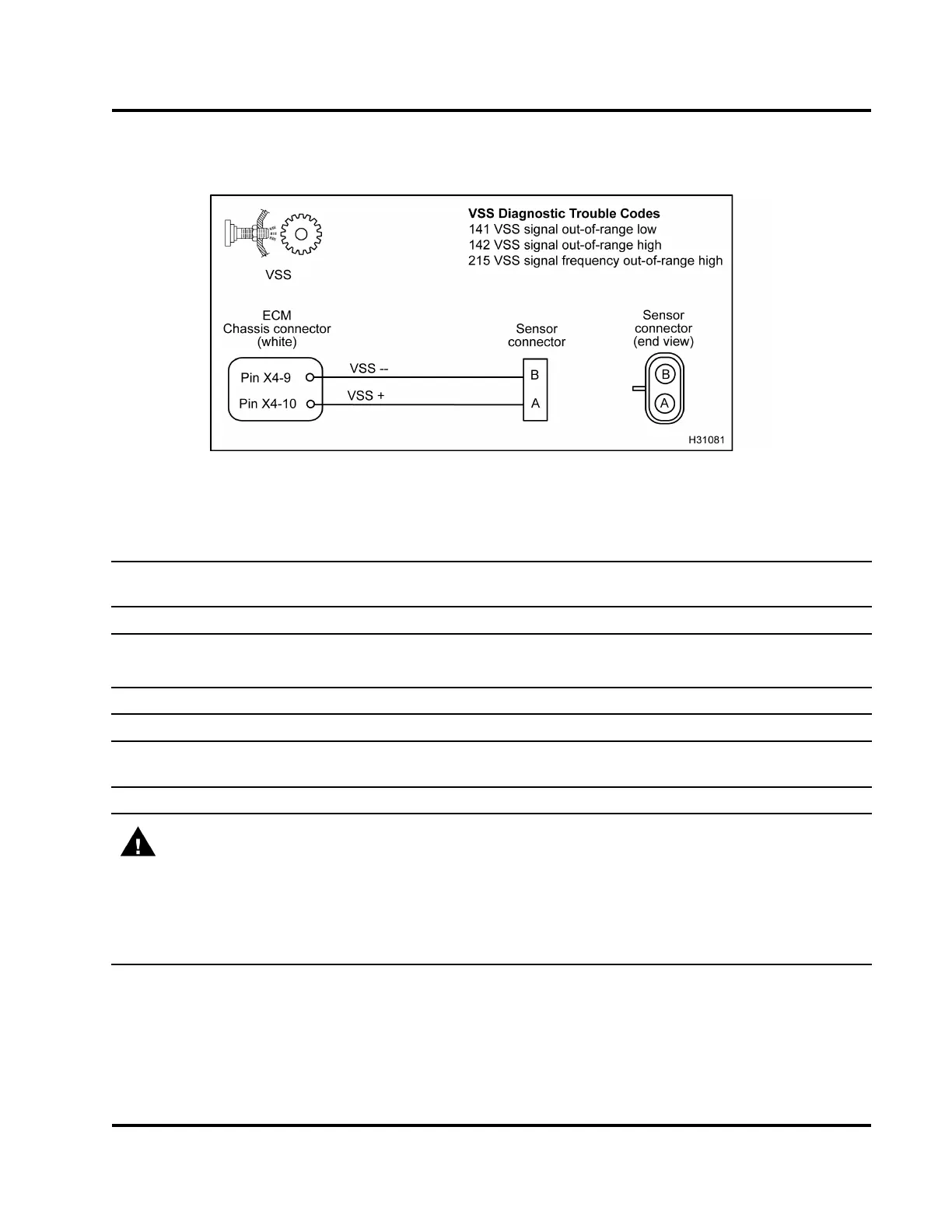
Transmissions)
Figure 509 VSS circuit diagram (manual transmissions)
The VSS circuit requires the use of vehicle circuit diagrams. See truck Chassis Electrical Circuit Diagram
Manual for circuit numbers, connector and fuse locations.
Connector Voltage Checks (Disconn
ect harness from sensor. Inspect for bent p ins or corrosion. Turn the
ignition switch to ON.)
Test Point
Spec Comment
Btognd 2Vto3V
Atognd 2Vto3V
ECM pull up voltage when sensor disconnected. If no
voltage present, check for open or short to ground.
Sensor Resi stan c e Checks (Che
ck with sensor disconnected and ignition switch OFF.)
BtoA
600 Ω to 800 Ω Manual transmission (measure resistance through sensor)
Sensor and Circuit Resistance Checks (Check with breakout box connected [X4 only] to engine harness
only with VSS connected. Inspect for bent pins or corrosion.)
X4–10 to X4–9
600 Ω to 800 Ω Manual transmission (me
asure resistance through s ensor)
WARNING: To avoid seriou
s personal injury, possible death, or damage to the engine or vehicle,
always disconnect main n
egative battery cable first. Always connect the main negative battery cable
last.
Connector Resistance C
hecks to Chassis Ground (Turn the ignition switch to OFF. Disconnect chassis
connector 9260
1
.Dis
connect negative battery cable. Disconnect harness from sensor. Use disconnected
negative battery cab
le for ground test point.)
A to gnd cable
>1kΩ If < 1 kΩ, check for short to ground.
B to gnd cable
>500Ω If < 500 Ω, check for short to ground.
EGES-270-1
Read all safety instructions in the "Safety Information" section of this manual before doing any procedures.
Follow all warnings, cautions, and notes.
© August 2008 Navistar, Inc.
 Loading...


