7 ELECTRONIC CONTROL SYSTEMS DIAGNOSTICS 373
ECM / IDM Communications (Electronic Control
Module / Injector Driver Module)
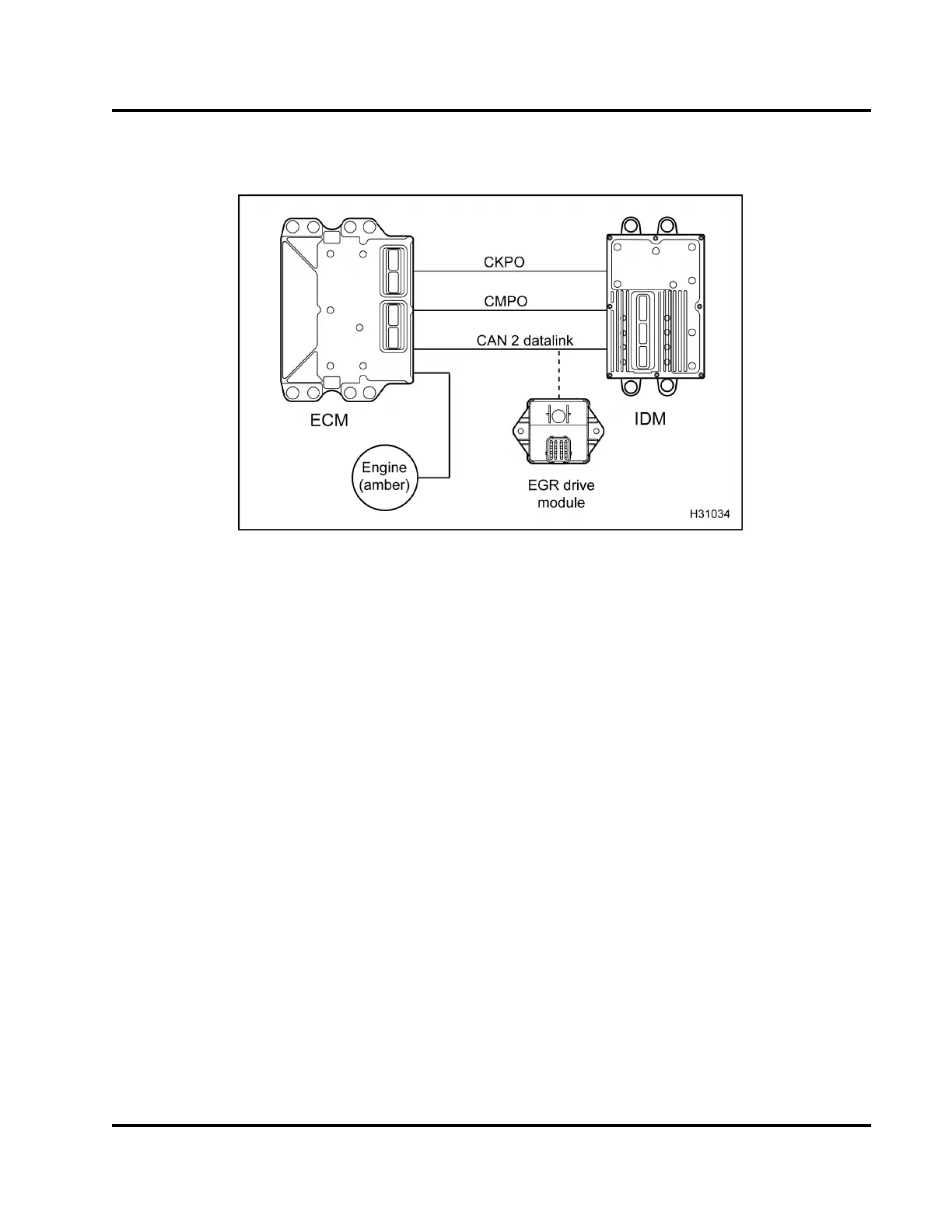
Figure 421 Function diagram for the ECM / IDM communication system
The function diagram for the ECM / IDM
communication system includes the following:
•ECM
•IDM
• Exhaust Gas Recirculation (EGR) drive module
• Crankshaft Position Output (CKPO) signal
• Camshaft Position Output (CMPO) signal
• Controller Area Network (CAN 2) datalink
• ENGIN E lamp (am ber)
Function
The ECM provides two output c hannels to aid the IDM
with engine speed and position signals. The C KPO
and CMPO channels are in phase with the CKP and
CMP signals received by the ECM.
The ECM an d IDM are in continuous communication.
The CKPO and CMPO signals are generated when
the ECM switches these circuits to ground. The IDM
uses these signals for engine speed and timing.
The CAN 2 datalink is a bidirectional communication
line between the ECM, IDM, and EGR drive module.
The E CM, IDM, and EGR drive module use the
datalink to send operating strategies, sensor
information, diagnostic demands, and Diagnostic
Trouble Codes (DTCs).
NOTE: The engine will not operate without the CAN 2
datalink, CKPO, o r CMPO signal.
EGES-270-1
Read all safety instructions in the "Safety Information" section of this manual before doing any procedures.
Follow all warnings, cautions, and notes.
© August 2008 Navistar, Inc.
 Loading...


