460 7 ELECTRONIC CONTROL SYSTEMS DIAGNOSTICS
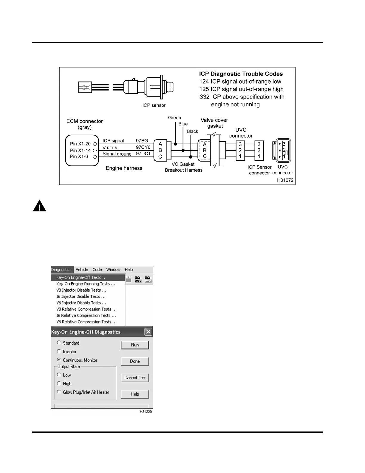
ICP Operational Diagnostics
WARNING: To avoid serious personal injury,
possible death, or damage to the engine or vehicle
– comply with the following:
Be careful to avoid rotatin g parts (belts an d fan)
and hot engine surfaces.
1. Using EST, open the D_ContinuousMonitor.ssn.
Figure 464 Continuous Monitor Test
2. To monitor signal voltage, run KOEO Continuous
Monitor Test.
3. Monitor ICP signal v oltage. Verify an active DTC
for the ICP circuit.
4. If code is active, do step 6 and 7 to check circuit
for the ICP sensor using the following tables.
• Circuit Chec ks for ICP Sensor – ECM to Valv e
Cover Gasket Connector
• Circuit Checks for ICP Sensor – ECM to ICP
Sensor
5. If code is inactive, wiggle connectors and wires
at all suspected problem loca tio ns. If circu it
continuity is interrupted, the EST display DTCs
related to the condition.
6. Disconnect engine harness from valve cover
gasket connector.
NOTE: Inspect connectors for damaged pins,
corrosion, or loose pins. Repair if necessary.
7. Connect VC Gasket Breakout H arness to engine
harness only.
EGES-270-1
Read all safety instructions in the "Safety Information" section of this manual before doing any procedures.
Follow all warnings, cautions, and notes.
© August 2008 Navistar, Inc.
 Loading...


