7 ELECTRONIC CONTROL SYSTEMS DIAGNOSTICS 351
CKP Sensor (Crankshaft Position)
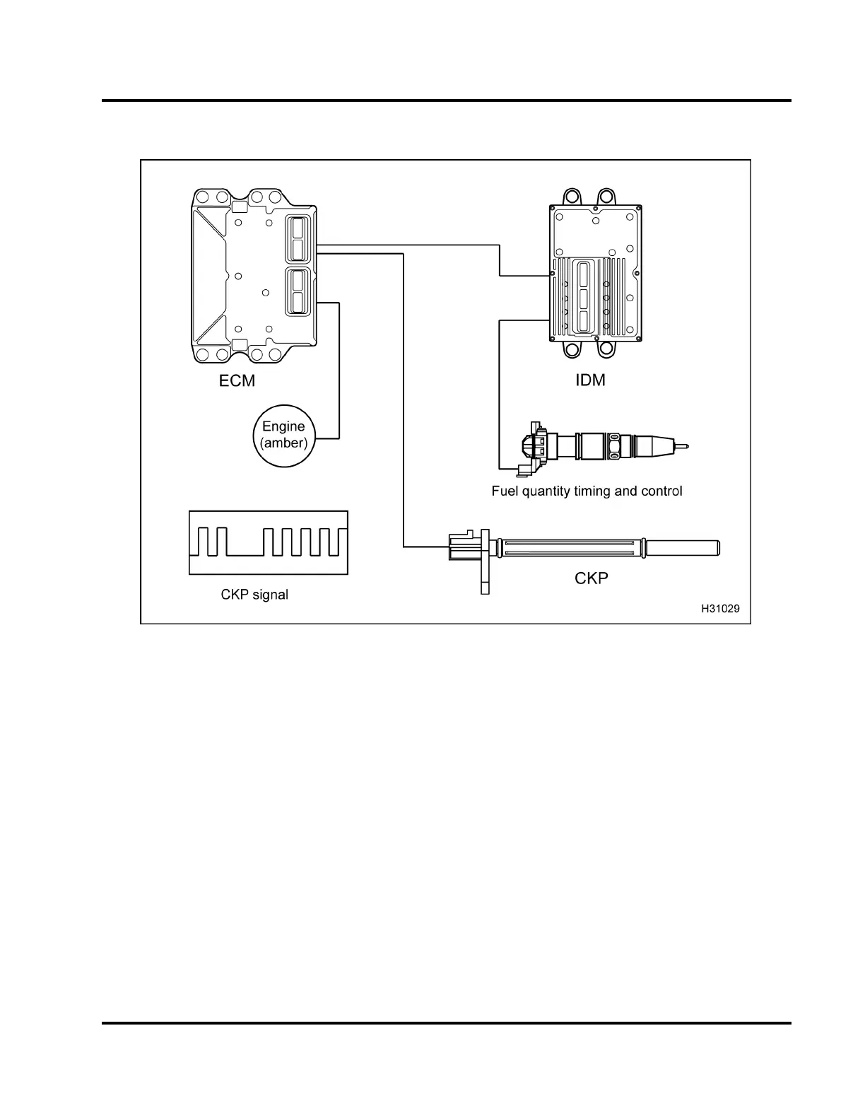
Figure 406 Function diag
ram for the CKP sensor
The function diagram f
or the CKP sensor includes the
following:
• CKP sensor
• Electronic Control M
odule (ECM)
• Injector Driver Modu
le (IDM )
• Fuel injector
• ENGIN E lamp (am ber)
Function
The C KP sensor provid
es the ECM with a signal
that indicates cran
kshaft speed and position. As the
crankshaft turns th
e CKP sensor detects a 60 tooth
timing disk on the
crankshaft. Teeth 59 and 60 are
missing. By comp
aring the CKP signal with the CMP
signal, the ECM c
alculates engine rpm and timing
requirements. The CKP
is installed in the top left sid e
of the flywheel housing
.
The sensor produces p
ulses for each tooth edge
that pa sses it. Cran
kshaft speed is derived from the
frequency of the CK
P sensor signal. The crankshaft
position is determ
ined by synchronizing the SYNC
toothwiththeSYN
C gap signals from the target
disk. From the CK
P signal frequency, the ECM
can calculate e
ngine rpm and timing requirements.
Diagnostic in
formation on the CKP input signal
is obtained by
performing accuracy checks on
frequency, a
nd duty cycle with software strategies.
NOTE: The lon
g CKP sensor, used with
Internation
al® DT 466, DT 570, and HT 570
diesel engi
nes, is the Camshaft Position (CMP)
sensor use
d with other International® diesel engines.
EGES-270-1
Read all safety instructions in the "Safety Information" section of this manual before doing any procedures.
Follow all warnings, cautions, and notes.
© August 2008 Navistar, Inc.
 Loading...


