444 7 ELECTRONIC CONTROL SYSTEMS DIAGNOSTICS
IAH System (Inlet Air Heate r)
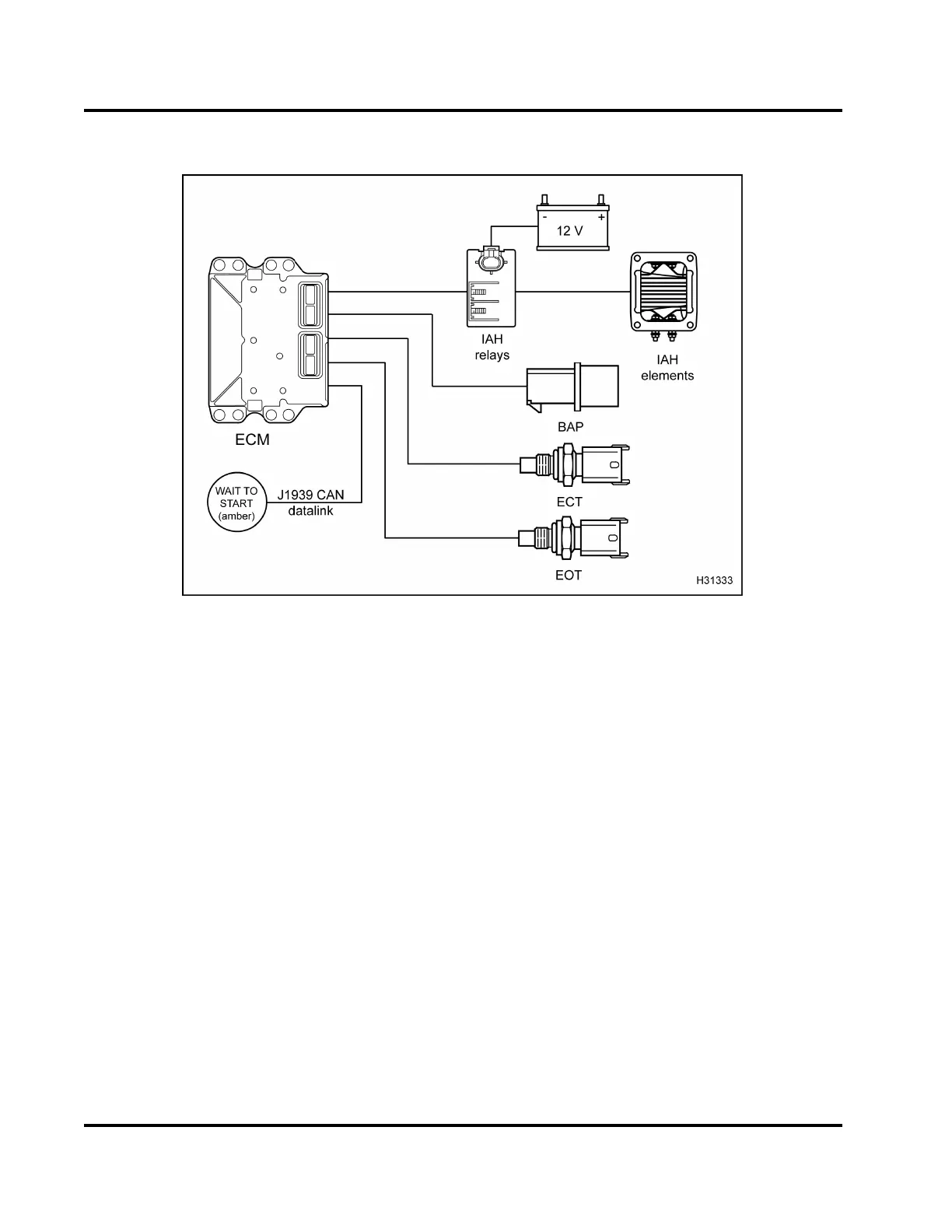
Figure 453 Function diagram for the IAH system
The function diagram for the IAH system includes the
following:
•IAHrelays
• IAH relay connectors
• IAH elements
• Electronic Control Module (ECM)
• Barometric Absolute Pressure (BAP) sensor
• Engine Coolant Temperature (ECT) sensor
• Engine Oil Temperature (EOT) sensor
• Battery
• WAIT TO START lamp (amber)
Function
The Inlet Air Heater (IAH) system warms the incoming
air supply prior to crankin g to aid co ld engine starting
and reduce white smoke during warm-up.
The ECM is programmed to energize the IAH
elements through the IAH relays while monitoring
certain programmed conditions for engine coolant
temperature, engine oil temperature, and atmospheric
pressure.
The ECM m onitors battery voltage and uses rea dings
from the ECT, EOT, and BAP sensor to determine
theamountoftimethattheWAITTOSTARTlampis
on, as well as the activation of the IAH system. The
WAIT TO START lamp indicates when the IAH relays
are activated and the elements are heating. The IAH
system on-time can vary between zero seconds to
forty-five seconds, depending on the ECT, EOT, and
BAP sensor readings.
IAH elements are activated for a longer time period if
the engine is cold or the barometric pressure is low
(high altitud e).
The engine is ready to start when the WAIT TO START
lamp is turn ed off by the ECM.
NOTE: The WAIT TO START lamp on-time is
independent from the IAH system on-time.
EGES-270-1
Read all safety instructions in the "Safety Information" section of this manual before doing any procedures.
Follow all warnings, cautions, and notes.
© August 2008 Navistar, Inc.
 Loading...


