7 ELECTRONIC CONTROL SYSTEMS DIAGNOSTICS 455
IAT Pin-Point Diagnos tics
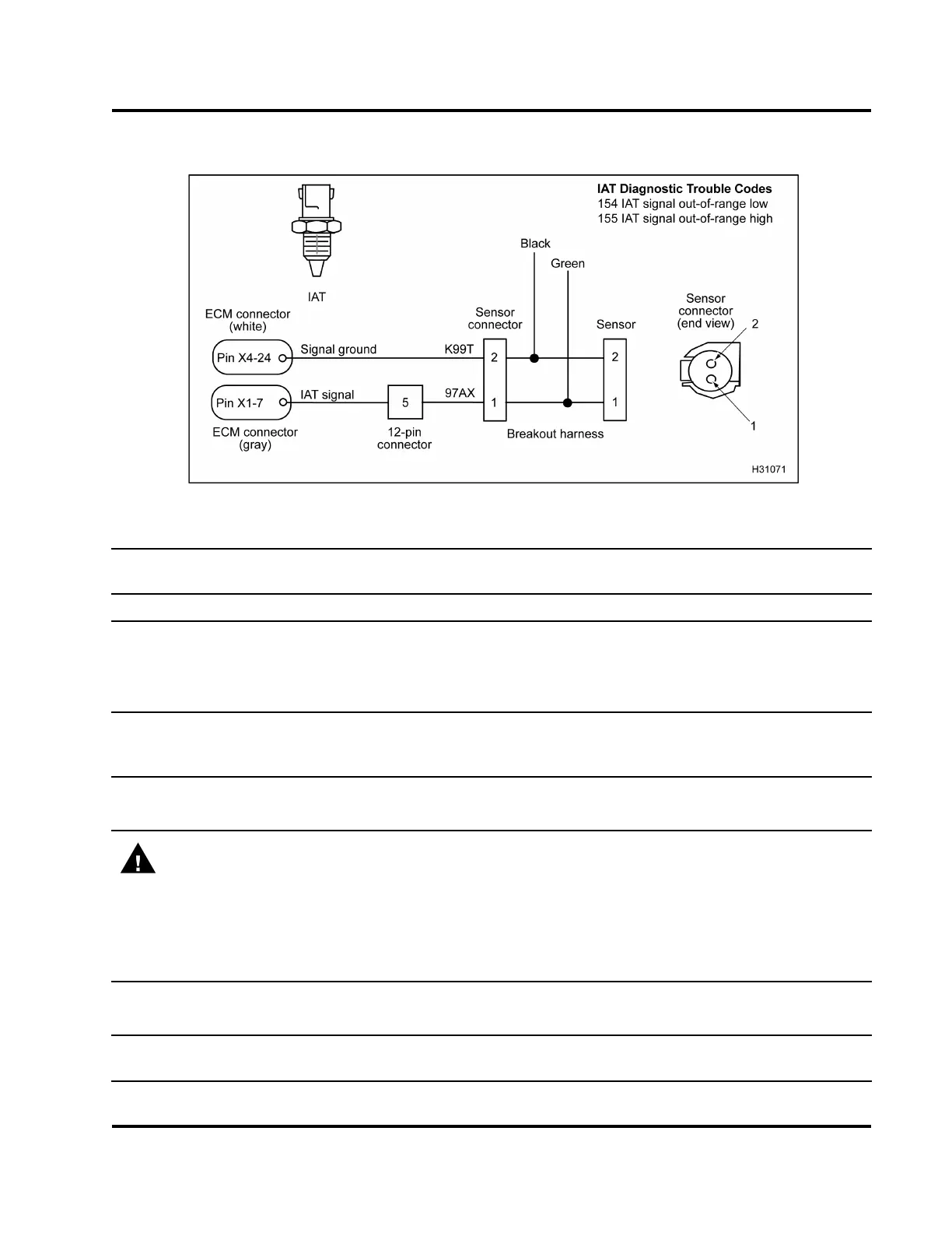
Figure 460 IAT circuit diagram
Connector Voltage Checks to Ground (Disconnect harness from sensor. Inspect for bent pins or corrosion.
Connect breakout harness to engine harness only. Turn the ignition switch to ON.)
Test Point
Spec Comment
2 to g nd 0 V to 0.25 V
Signal ground (No voltage expected). If > 0.25 V, signal wire is
shortedtoV
REF
or B+.
1tognd 4.6Vto5.0V
Pull up voltage, if no voltage, circuit has open, high resistance,
or short to ground.
Connector Resistance Check
s to ECM Chassis Ground (Turn the ignition switch to OFF. Disconnect
harness from sensor. Conne
ct breakout harness to engine harness only. Disconnect chassis connector
9260
1
.)
2toPinA(9260) <5Ω If > 5 Ω, check for open circuit.
1toPinA(9260) >1kΩ If < 1 kΩ, check for short to ground within wiring harness.
WARNING: To avoid serious personal injury, possible death, or damage to the engine or vehicle,
always disconnect main negative battery cable first. Always connect the main negative battery cable
last.
Connector Resistance Checks to Chassis Ground (Turn the ignition switch to OFF. Disconnect chassis
connector 9260
1
. Disconnect negative battery cable. Disconnect harness from sensor. Connect breakout
harness to engine harness only. Use disconnected negative battery cable for ground test point.)
2togndcable
> 500 Ω If < 500 Ω , check for
short to ground.
1togndcable
>1kΩ If < 1 kΩ, check for short to ground.
Harness Resistance Checks (Connect breakout box to engine harness [X1 only] and chassis harness
[X4 only].)
EGES-270-1
Read all safety instructions in the "Safety Information" section of this manual before doing any procedures.
Follow all warnings, cautions, and notes.
© August 2008 Navistar, Inc.
 Loading...


