294 7 ELECTRONIC CONTROL SYSTEMS DIAGNOSTICS
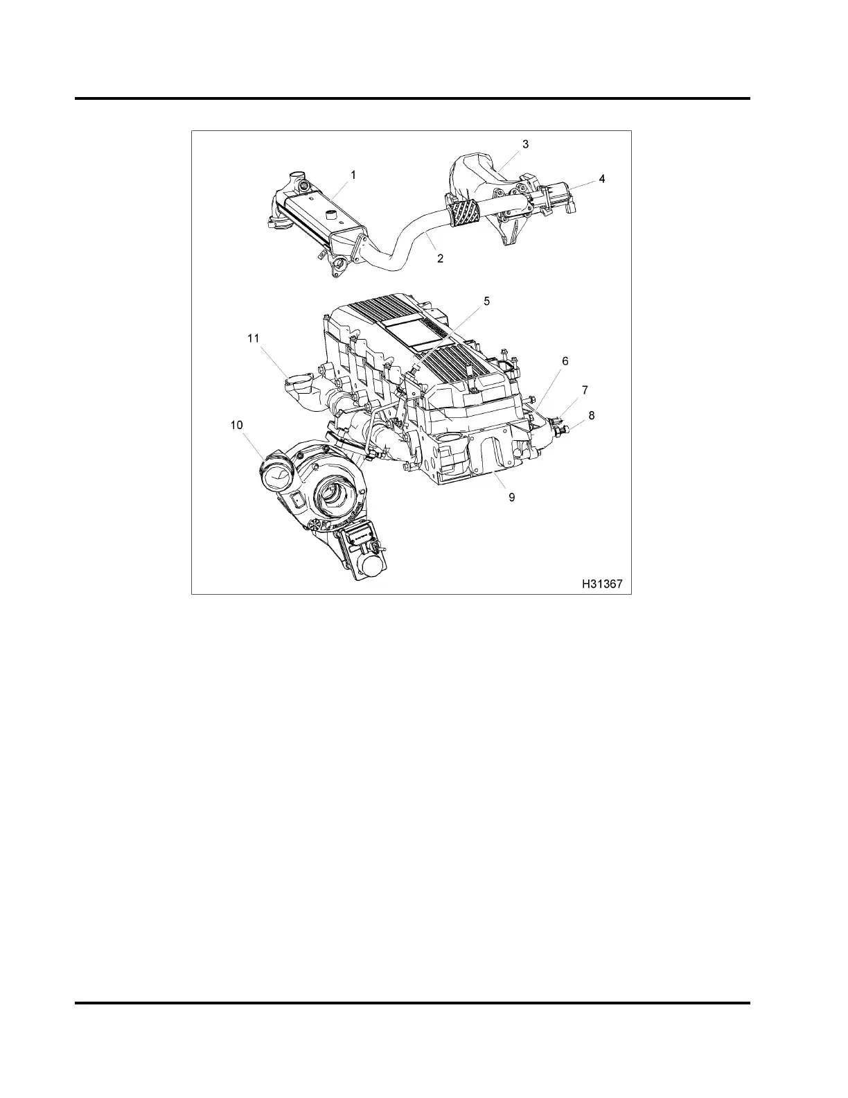
Figure 374 AMS components
1. EGR cooler
2. EGR tube assembly crossov
er
3. Intake and EGR mixer duct
(heater optional)
4. EGR valve assembly
5. EBP sens or
6. Intake manifold
7. MAT senso r
8. MAP sensor
9. Cylind er he ad
10. Turbocharger (VGT)
11. Exhaust manifold
AMS Operation
Function
The Variable Geometry T
urbocharger (VGT) has
actuated vanes in the
turbine housing. The vanes
modify flow character
istics of exhaust gases through
the turbine housing
. The be nefit is the ability to
control b oost press
ure for various engine speeds and
load conditions.
TheVGTisaclosedl
oop system that uses the
Exhaust Back Pres
sure (EBP) sensor to provid e
feedback to th e E
lectronic Control M od ule (ECM).
The ECM uses the E
BP sensor to continuously
monitor EBP and adjust t
he duty cycle to the VGT to
match engine requirem
ents.
The VGT actuator is a con
trol module that contains
a microchip and a DC mot
or. The VGT actuator
is located below the
turbocharger. The microchip
operates a DC motor w
hich rotates a crank lever
controlling the va
ne position in the turbine housing.
The position of th
e vanes is based off the pulse width
modulated signal
sent from the ECM.
Actuated vanes ar
e mounted around the inside
circumference o
f the turbine housing. A unison ring
links all the va
nes. When the unison ring moves,
all vanes move t
o the same position. Unison ring
EGES-270-1
Read all safety instructions in the "Safety Information" section of this manual before doing any procedures.
Follow all warnings, cautions, and notes.
© August 2008 Navistar, Inc.
 Loading...


