7 ELECTRONIC CONTROL SYSTEMS DIAGNOSTICS 469
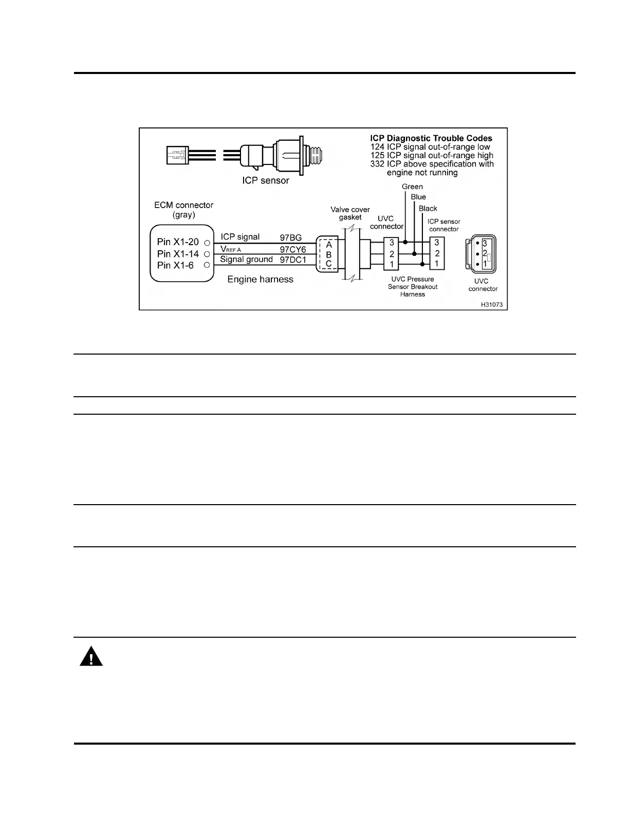
ICP Pin-Point Diagnostics (ECM to ICP Sensor–
valve cover removed)
Figure 469 ICP circuit diagram with UVC Pressure Sensor Breakout Harness
Connector Voltage Checks to Ground with Valve Cover Removed (Disconnect sensor from UVC
connector and connect UVC Pressure Sensor Breakout Harness to UVC connector only. Turn the ignition
switch to ON.)
Test Point
Spec Comment
1tognd 0Vto0.25
V
Signal ground (no voltage expect
ed). If > 0.25 V, check ground circuit for
open or high resistance and check
for short to V
REF
or B+.
2tognd 5V±0.5V
If voltage is not to spec, V
REF
circuit is shorted to ground, shorted to B+, or
open.
3tognd 0Vto0.25
V
If voltage > 0.25 V, signal circuit is shorted to V
REF
or B+.
Connector Resistance Checks to ECM Chassis Ground with Valve Cover Removed (Turn the ignition
switch to OFF. Disconnect sensor from UVC connector. Disconnect chassis connector 9260
1
. Connect UVC
Pressure Sensor Breakout Harness to UVC connector only.)
1toPinA
(9260)
<5Ω If > 5 Ω, check for open circuit.
2toPinA
(9260)
>500Ω If < 500 Ω, check for short to ground within wiring harness.
3toPinA
(9260)
>1kΩ If < 1 kΩ,checkforsh
ort to ground within wiring harness.
WARNING: To avoid serious personal injury, possible death, or damage to the engine or vehicle,
always disconnect main negative battery cable first. Always connect the main negative battery cable
last.
EGES-270-1
Read all safety instructions in the "Safety Information" section of this manual before doing any procedures.
Follow all warnings, cautions, and notes.
© August 2008 Navistar, Inc.
 Loading...


