290 7 ELECTRONIC CONTROL SYSTEMS DIAGNOSTICS
Pin-Point Diagnostics
Some Pin-Point Diagnostic tests use the
MasterDiagnostics® Output State Tests. For
help, see “Diagnos tic Software Operatio n” in Section
3 (page 68) for procedure to run the Low and High
Output State Tests.
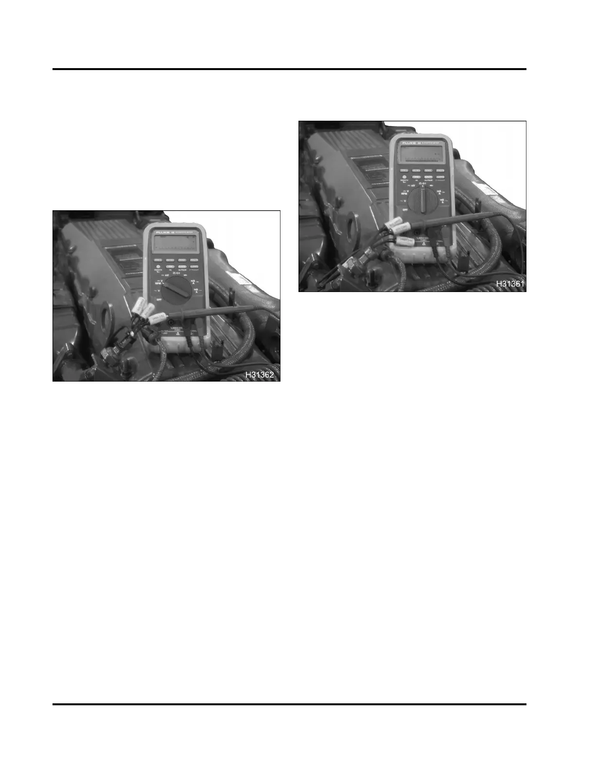
Connector Voltage Checks to Ground
Figure 370 V
REF
check
Procedure
1. TurntheignitionswitchtoON.
2. Connect breakout harness to the harness only.
3. Measure voltage at each pin with a DMM.
4. Compare sensor or actuator voltage readings with
the expected voltages. See Circuit Diagnostics in
this section for circuit spec ifications.
If a breakout harness is not available, use the
correct tool from Terminal Test Adapter Kit. Do not
directly probe the connector pins with the DMM
leads. For a circuit with an expected voltage, this
test will verify circuit integrity.
5. TurntheignitiontoOFF.
For circuits w ith ou t an expected voltage, this test will
determine if that circuit is shorted or incorrectly wired
to ground, V
REF
, B + or other voltage sources.
Connector Resistance Checks to ECM Chassis
Ground
Figure 371 Resistance check to ECM chassis
ground
Procedure
NOTE: The truck Chassis Electrical Circuit Diagram
Manual should always be used for chassis g round
circuit information.
1. Disconnect chassis connector 9260.
NOTE: Connector 9260 is a 2-wire connector
usually located in the battery box. Pin A is the
chassis ground connection for the ECM and IDM.
See truck Chassis Electrical Circuit Diagram
Manual for complete chassis side ECM and IDM
ground circuit information.
2. Connect breakout harness to harness only.
3. Use breakout h arne ss to measure re sistance from
the lead of the breakout harness to the connector
9260 Pin A.
See Circuit Diag n os tics in th is section for circuit
specifications.
Sensor signal ground circuits should measure
less than 5 ohms .
V
REF
and signal circuits should measure more than
1 k ohm.
The control side of an actuator will measure more
than 1 k ohms, but the expected voltage for the
other side of the actuator circuit will measure the
EGES-270-1
Read all safety instructions in the "Safety Information" section of this manual before doing any procedures.
Follow all warnings, cautions, and notes.
© August 2008 Navistar, Inc.
 Loading...


