526 7 ELECTRONIC CONTROL SYSTEMS DIAGNOSTICS
Function
The VGT actuator is a control module that cont ains
a microchip and a DC motor. The VGT actuator
is located below the turbocharger. The microchip
operates a DC motor which rotates a crank lever
controlling the vane position in the turb ine housing.
The position of the vanes is based off the pulse w idth
modulated signal sent from the ECM.
Actuator control for the vane position is achieved by
setting a pulse width modulated signal from the ECM
in response to the fo llowing:
• Engine speed
• Desired fuel quantity
• Boost (manifold air pressure)
• Exhaust back pressure and altitude
VGT Circuit Operation
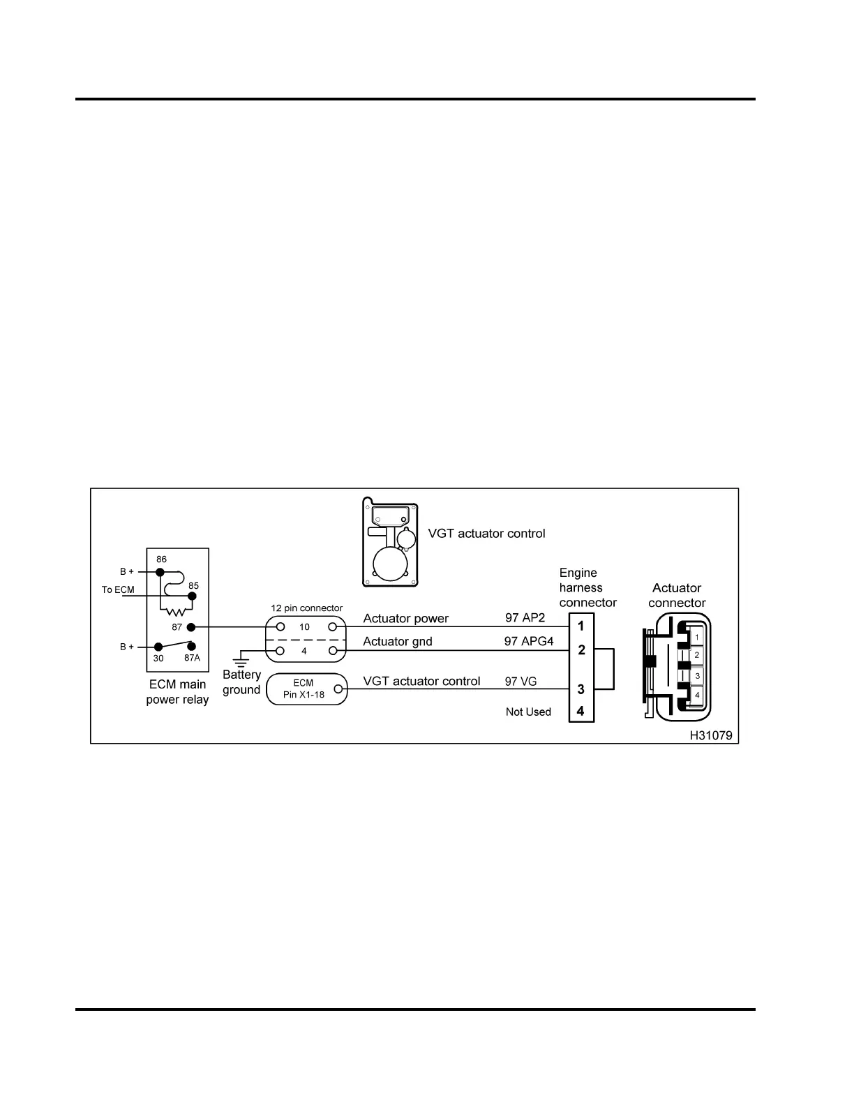
Figure 499 VGT circuit diagram
The VGT actuator receives power at Pin 1, through the
12-pin connector Pin 10, from the ECM main power
relay Pin 87. Ground for the VGT actuator is supplied
at Pin 2, through the 12-pin connector Pin 4 from
battery ground. The ECM controls the VGT actuator
by sending a pulse width modulated signal from the
ECM, Pin X1-18 to the actuator harness connector Pin
3.
The VGT actuator is controlled by varying the
percentage of ON/OFF time of the VGT actuator
control signal to control module. A high duty cycle
indicates a high amount of exhaust back pressure is
being c ommanded. A low duty cycle indicates less
pressure being commanded.
Fault Detection / Management
When the engine is running, the ECM c an detect if
exhaust back pressure equals the desired pressure.
When measured exhaust back pressure does not
equal the desired pressure, the ECM will ignore the
EBP sensor signal and use a preset value based on
engine operating conditions.
EGES-270-1
Read all safety instructions in the "Safety Information" section of this manual before doing any procedures.
Follow all warnings, cautions, and notes.
© August 2008 Navistar, Inc.
 Loading...


