8 DIAGNOSTIC TOOLS AND ACCESSORIES 575
flows through the meter. The ammeter measures
current flow only when the circuit is powered up and
operating. The DMM is fused to measure up to 10
amps using the 10 A connection point.
Before measuring current flow, determine
approximately how many amps are in the circuit
to correctly connect the ammeter. The estimate of
current flow can easily be calculated. The resistance
of the light bulb is 2 ohms. Applying Ohm’s law,
current flowwillbe6amps(6amps=12V÷2
ohms). If the fuse is removed and an ammeter is
installed with the sw itch closed, 6 amps of current will
be measured flowing in the circuit. Notice that the
ammeter is installed in series so that all the current in
the circuit fl ows through it.
WARNING: To avoid serious personal injury
or possible death, always make sure the powe
ris
off before cutting, soldering, removing c
ircuit
components, or before inserting the digi
tal
multimeter for current measurements. E
ven
small amounts of current can be dang
erous.
Excessive current draw m e an s that mo
re current
is flowinginacircuitthanthefusea
nd circuit were
designed to handle. Excessive cur
rent draw will
open fuses and circuit breakers, a
nd will also quickly
discharge batteries. An ammeter
can diagnose these
conditions.
Reduced current draw will cau
seadevice(an
electric window motor, fo r ex
ample) to operate poorly.
Increased circuit resistan
ce will cause lower current
flow (often due to loose or co
rroded connections).
Ohmmeter
CAUTION: To prevent dama
ge to the test m eter, only
use the ohmmeter on circ
uits when the power is OFF.
Power from 12 V systems
may damage the meter.
The ohmmeter measure
s resistance (ohms) in a
circuit. Ohmmeters u
seasmallbatterytosupply
voltage and current
flow through the circuit being
tested. Based on Ohm
’s Law, the ohmmeter
calculates resist
ance in the circuit by measuring
the voltage of the
meter battery and the amount of
current flow in th
e circuit. Range selec tio n and meter
adjustment are
not necessary with the DMM.
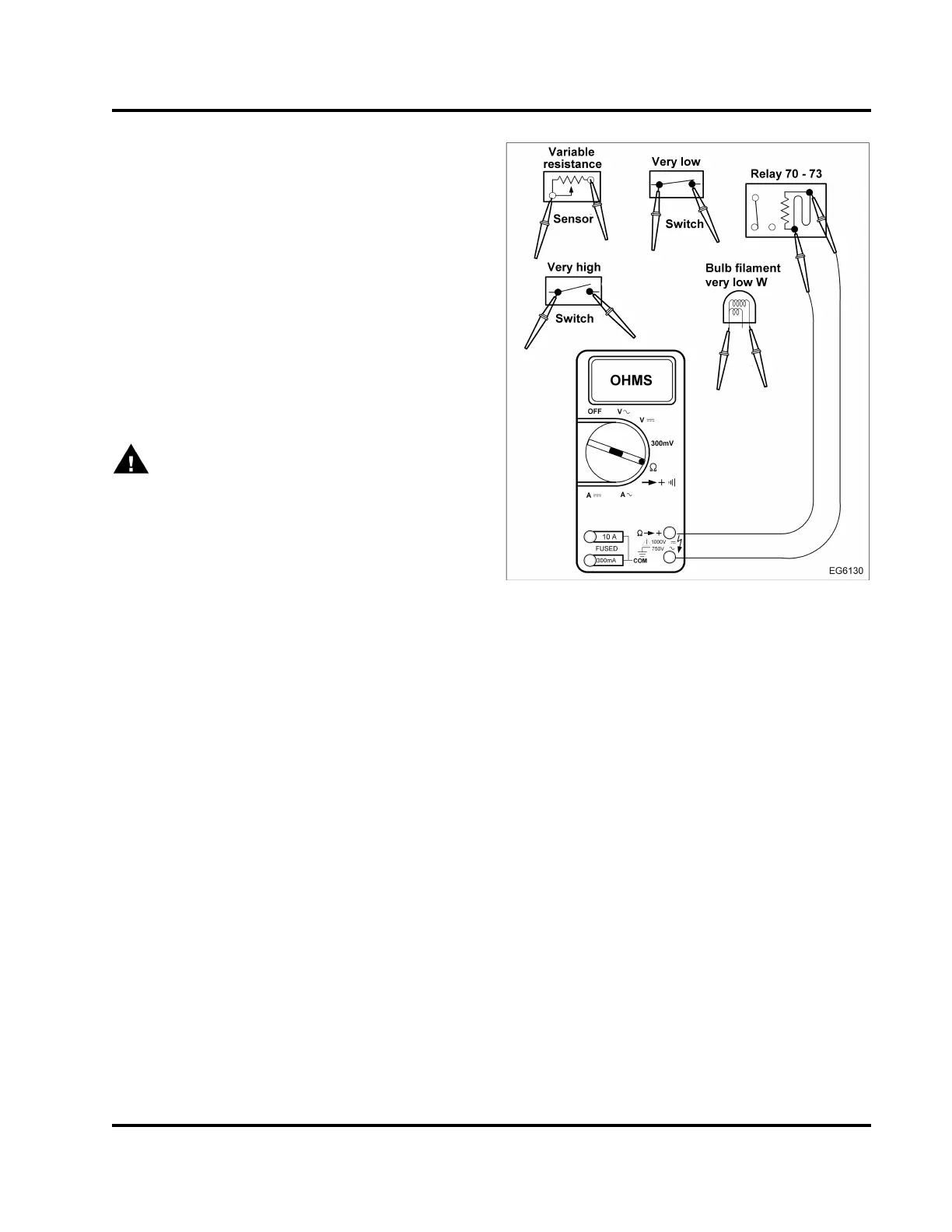
Figure 558 Measuring resistance
Resistance measurements are used to determine
the resistance of a load or conductors, the value of
resistors and the operation of variable resistors.
To measure the resistance of a component or a
circuit, remove power from the circuit. Isolate the
component or circuit from other components and
circuits so that the meter current (from probe to
probe) only flows through the selected component or
circuit. When measuring the resistance of the load,
most of the current flow from the meter will go through
the indicator lamp because it has less resistance.
Remove one connector to the load. It is not always
apparent when a component must be isolated, so it
isagoodpracticetoisolateacomponentorcircuit
by disconnecting one circuit. Place the ohmmeter
leads across the component or circuit to display the
resistance in ohm s. When checking a sensor or
variable resistor such as the fuel level gauge, heating
the element or moving the arm should move the meter
through a range of resistance that can be compared
toaspecification.
EGES-270-1
Read all safety instructions in the "Safety Information" section of this manual before doing any procedures.
Follow all warnings, cautions, and notes.
© August 2008 Navistar, Inc.
 Loading...


