7 ELECTRONIC CONTROL SYSTEMS DIAGNOSTICS 495
IPR Circuit Operation
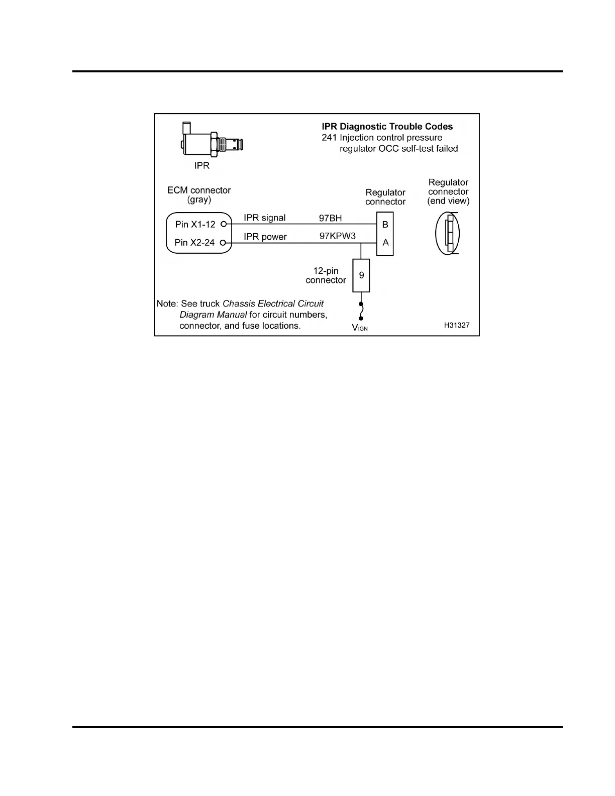
Figure 481 IPR circuit diagram
The IPR valve is supp lie d with vo
ltage at Pin A of
the IPR connector through 12–p
in connector (Pin 9)
from V
IGN
. The control of the i
njection control system
is gain ed by the ECM grounding
Pin B of the IPR
valvethroughPinX1-12ofth
e ECM. Precise control
is gained by varying the p
ercentage of ON/OFF time
of the IPR solenoid . A hig
h duty cycle indicates a
high amount of injectio
n control pressure is being
commanded. A low duty c
ycle indicates less pressure
being commanded.
Fault Detection / Ma
nagement
An open or short to gro
und in the ICP control circuit
can be detected by an
on demand output circuit
check during KOEO S
tandard Test. If there is a circuit
fault detected a Di
agnostic Trouble Code (DTC) will
be set. When the en
gine is ru nn ing, the E CM can
detect if the inj
ection control pressure is equal to
the desired pre
ssure. When the measured injection
control p ress
ure does not compare to the desired
pressure, the
ECM will ignore the measured ICP
signal and co
ntrols the engine with the desired value.
IPR Diagnost
ic Trouble Codes (DTCs)
DTCs are read
using the EST or by counting the
flashes from
the amber and red ENGINE lamp.
DTC 241
IPR OCC self-test failed
• DTC 241 is set by the ECM when the O u
tput
Circuit Check (OCC) test has fai
led after the
KOEO Standard Test has been r
un.
• DTC 241 can be set when a poor co
nnection to
the IPR solenoid or inoperat
ive IPR coil e xists.
• When DTC 241 is active the eng
ine will not
run and the amber ENGINE lamp
will not be
illuminated.
Tools
• EST with MasterDiagnost
ics® software
• EZ-Tech® interface cable
• Digital Multimeter (DM
M)
• Breakout Box
• Actuator Breakout Harne
ss
• Terminal Te st Adapter Ki
t
EGES-270-1
Read all safety instructions in the "Safety Information" section of this manual before doing any procedures.
Follow all warnings, cautions, and notes.
© August 2008 Navistar, Inc.
 Loading...


