5 HARD START AND NO START DIAGNOSTICS 175
Possible Causes
Low battery v oltage
• Failed batteries
• High-resistance at battery cable connections
• Wiring to the ECM
Low or no battery voltage to the ECM
• High-resistance or an open power feed circuit to
the ECM or ECM main power relay.
• The ECM power circuit fuse in battery box may be
open.
• ECM main power relay may have failed.
•V
IGN
circuit problem
• Failed ECM
Voltage Measurement at ECM with Breakout Box
NOTE: If the breakou t b ox was used to do Test 6 –
EST Data List, the following procedures do not have
to be done.
Use the following procedures when any of the
following situations exist:
• A Relay Breakout Harness is not available
• Expected voltages w ere not to spec, when using
the Relay Breakout Harness
• Voltages were to spec, using the Relay Breakout
Harness and Hard Start No Start Diagnostics is
complete–butaconcernremains
Tools
• Breakout Box
• Digital Multimeter (DMM)
Procedure
WARNING: To avoid serious personal injury,
possible death, or damage to the engine or
vehicle, read all safety instructi on s in the “Safety
Information” section of this manual.
NOTE: Batteries must be fully charged before doing
the following steps.
1. Turn the ignition switch to OFF and ensure all
accessories are turned off.
2. Remove two white connectors (X3 and X4) from
ECM.
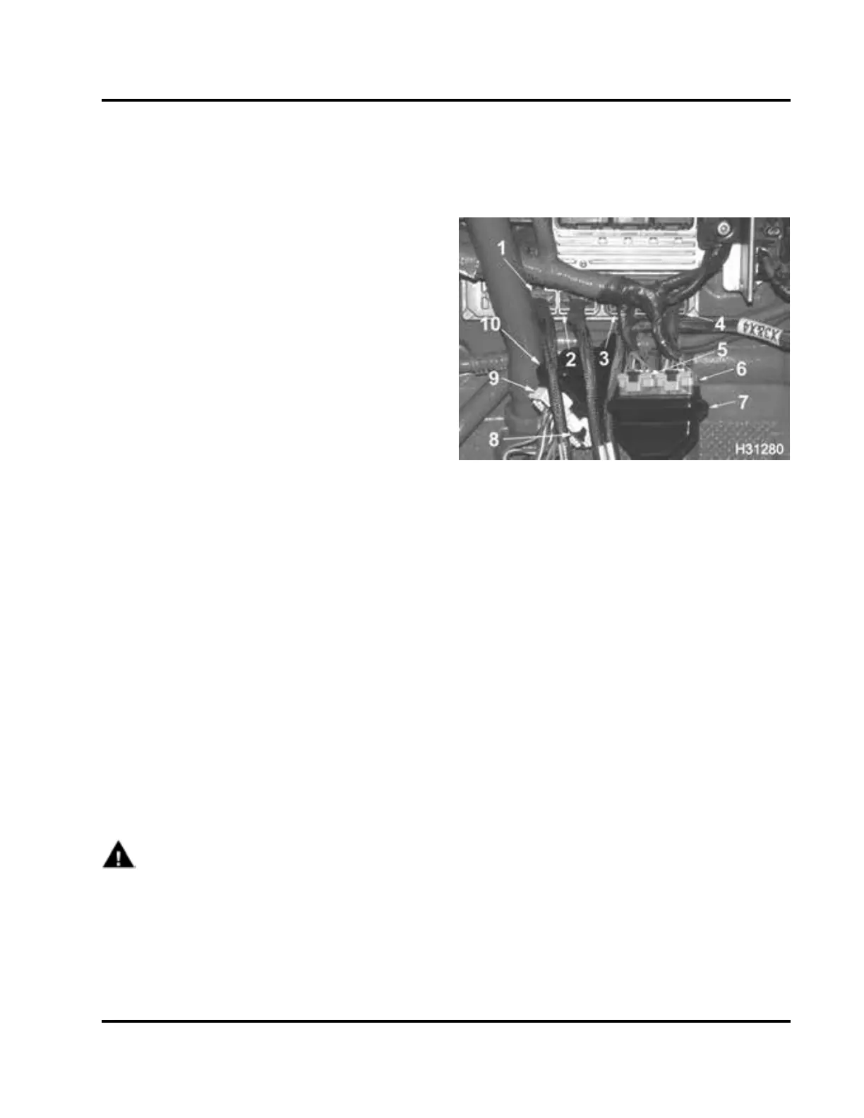
Figure 205 Engine and chassis breakout box
connections
1. Breakout box connector X4 to ECM
2. Breakout box connector X3 to ECM
3. Breakout box connector X2 to ECM
4. Breakout box connector X1 to ECM
5. Engine wiring harness ECM connector X2 to
breakout box header
6. Engine wiring harness ECM connector X1 to
breakout box header
7. Breako ut box header X1 and X2 engine to breakout
box
8. Chassis wiring harness connector to breakout box
header
9. Chassis wiring harness connector to breakout box
header
10. Breakout box header X3 and X4 breakout box to
chassis
3. Connect breakout box connectors (X3 and X4) to
connections on ECM.
4. Connect chassis harness connectors to breakout
box header (X3 and X4).
EGES-270-1
Read all safety instructions in the "Safety Information" section of this manual before doing any procedures.
Follow all warnings, cautions, and notes.
©August 2008 Navistar, Inc.
 Loading...


