458 7 ELECTRONIC CONTROL SYSTEMS DIAGNOSTICS
ICP Circuit Operation
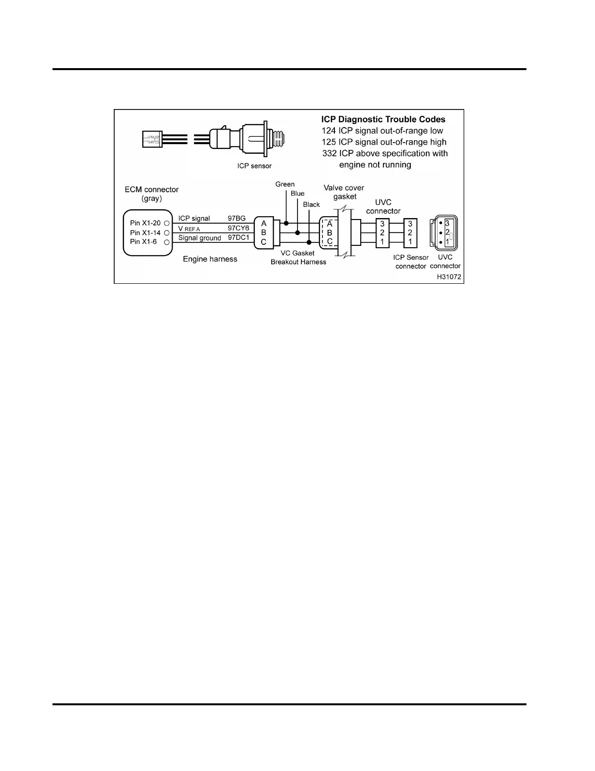
Figure 462 ICP circuit diagram
TheICPsensorissupplieda5Vreferencesignalat
Pin 2 through valve cover gasket Pin B from ECM Pin
X1–14. The ICP sensor is supplied a signal ground at
Pin 1 through valve cover gasket Pin C from ECM Pin
X1–6. The ECM monitors the ICP signal from sensor
Pin3throughvalvecover gasket Pin A to ECM Pin
X1–20.
Fault Detection / Management
The ECM continuously monitors the signal of the ICP
sensor to determine if the signal is within an expecte d
range. If the ECM detects a voltage greater or less
than exp ected, the ECM w ill set a DT C, illuminate the
amber ENGINE lamp, ignore the ICP sensor signal,
anduseapresetvaluebasedonengineoperating
conditions.
ICP D iagnostic Trouble Codes (DTCs)
DTCs are read using the EST or by counting the
flashes from the amber and red ENGINE lamps.
DTC 124
ICP signal out-of-range low
• DTC 124 is set by the ECM if signal voltage is less
than 0.039 V fo r more than 0.1 seco nd.
• DTC 124 can be set due to an open or short to
ground on the signal circuit, a failed ICP sensor
or an open V
REF
circuit or V
REF
short to ground.
• When DTC 124 is active the amber ENGINE lamp
is illuminated.
DTC 125
ICP signal out-of-ran ge high
• DTC 125 is set by the ECM if the signal voltage is
greater than 4.9 V for more than 0.1 second.
• DTC 125 can be set due to a signal c ircuit shorted
to V
REF
or B+, or a failed ICP sensor.
• When DTC 125 is active the amber ENGINE lamp
is illuminated.
EGES-270-1
Read all safety instructions in the "Safety Information" section of this manual before doing any procedures.
Follow all warnings, cautions, and notes.
© August 2008 Navistar, Inc.
 Loading...


