194 5 HARD START AND NO START DIAGNOSTICS
• End plugs in high-pressureoil rail (Figure238)
• Loose brake shut-off valve (optional) (Figure
238)
11. Replace or repair components, if necessary.
12. Install the valve cover following the procedures in
the Engine Service Manual.
NOTE: Make sure all under valve cover wiring is
routed correctly. Follow procedures in the Engine
Service M anual.
• If engine is equipped with Diamond Logic®
Engine Brake, and the high-pressure oil
manifold has been removed, adjust the
engine brake lash. Follow the procedure in
Section 6 - Performance Diagnostics, Brake
Lash.
14.5 – IPR Function
WARNING: To avoid serious personal injury,
possible death, or damage to the engine or
vehicle, read all safety instructions in the “Safety
Information” section of this manual.
1. Remove ICP sensor adapter and spare ICP
sensor from test hose assembly.
Figure 241 ICP Test Kit
1. ICP sen sor adapter
2. Fitting 13/16-16 NPT
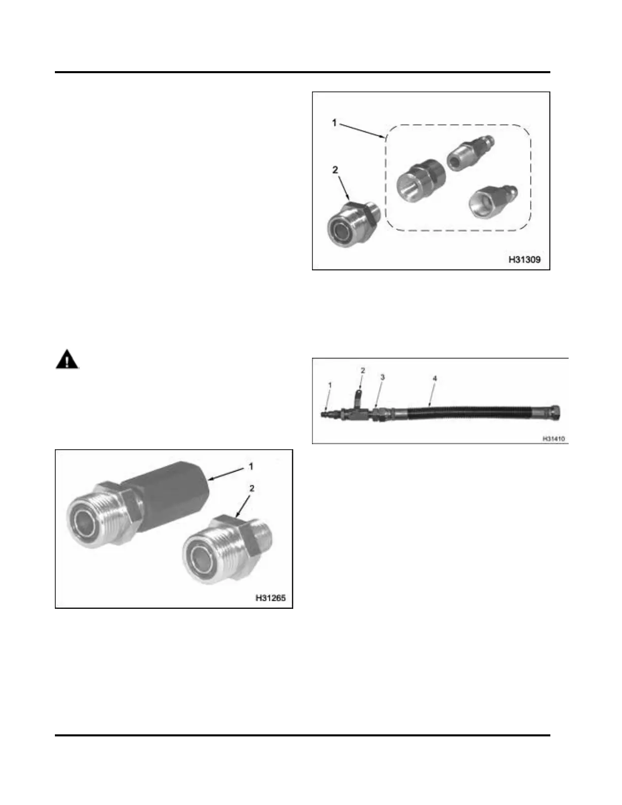
Figure 242 13/16-16 NPT fitting and air chuck
adapters
1. Air chuck adapters
2. Fitting, 13/16-16 NPT
Figure 243 High-pressure oil hose, fitting, and
air chuck
1. Air chuck
2. Shut-off valve
3. 13/16-16 NPT fitting
4. High-pressure hose
EGES-270-1
Read all safety instructions in the "Safety Information" section of this manual before doing any proced ures.
Follow all warnings, cautions, and notes.
©August 2008 Navistar, Inc.
 Loading...


