1 ENGINE SYSTEMS 21
Variable G eometry Turbocharger (VGT)
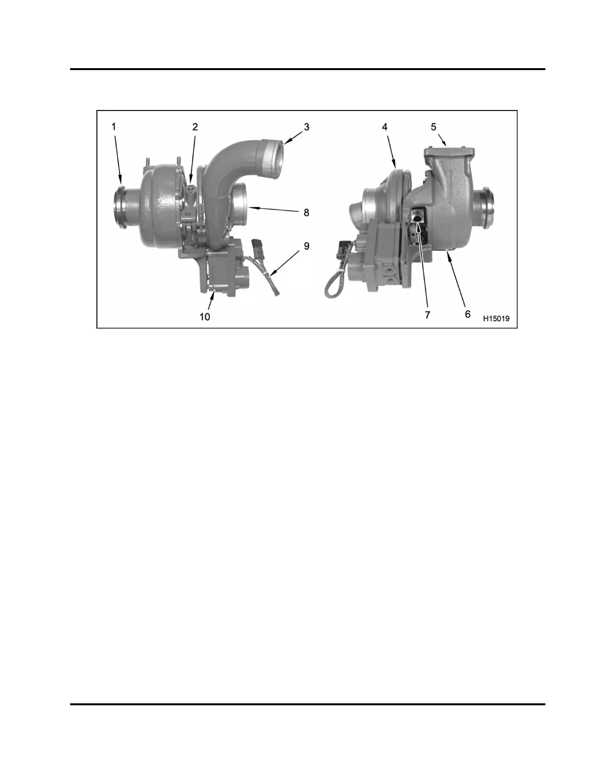
Figure 12 Variable Geometry Turbocharger (VGT)
1. Turbine outlet
2. Oil supply port
3. Compressor outlet
4. Compressor housing
5. Turbine inlet
6. Turbine housing
7. Oil dra in port
8. Compressor inlet
9. Electrical conne ctor and wire
10. Turbocharger control module
The Variable Geometry Turbocharger (VGT) has
actuated vanes in the turbine housing. The vanes
modify flow characteristics of exhaust gases through
the turbine housing. The benefit is the ability t o contro l
boost pressure for various engine speeds and load
conditions. An additional benefit is lower emissions.
EGES-270-1
Read all safety instructions in the "Safety Information" section of this manual before doing any procedures.
Follow all warnings, cautions, and notes.
© August 2008 Navistar, Inc.
 Loading...


