7 ELECTRONIC CONTROL SYSTEMS DIAGNOSTICS 391
ECT Sensor (Engine Coolant Temperature)
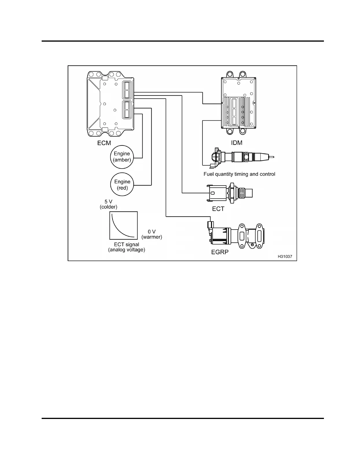
Figure 428 Function diagram for the ECT sensor
The function diagram for the ECT sensor includes the
following:
• ECT sensor
• Electronic Control Module (ECM)
• Exhaust G as Recirculation (EGR)
• Injector Drive Module (IDM)
• Fuel injector
• Variable Geometry Turbocharger (VGT)
• ENGIN E lamp (amber and red)
Function
The ECT sensor is a thermistor sensor installed in the
water supply housing (Freon® compressor bracket),
right of the fl at idler pulley assembly. The ECM
supplies a 5 V reference signal which the ECT sensor
uses to produce an analog voltage that indicates
temperature.
The ECT sensor changes resistance when exposed
to different temperatures. As the coolant temperature
decreases, the resistance of the thermistor increases.
This causes the signal voltage to increase. As the
coolant temperature increases, the resistance of the
thermistor decreases. This causes the signal voltage
to decrease.
EGES-270-1
Read all safety instructions in the "Safety Information" section of this manual before doing any procedures.
Follow all warnings, cautions, and notes.
© August 2008 Navistar, Inc.
 Loading...


