256 6 PERFORMANCE DIAGNOSTICS
16. Crankcase Pressure
Figure 333
Purpose
To measure the condition of the power cylinders
Tools
• Magnehelic gauge on gauge bar or water
manometer
• Crankcase pressure test adapter
Procedure
WARNING: To avoid serious personal injury,
possible death or damage to the engine or
vehicle, read all safety instructions in the “Safety
Information” section of this manual.
1. See “DT 466 Performance Specifications” –
Appendix A (page 595) or “DT 570 and HT 570
Performance Specifications” – Appendix B (page
619) for specifications and record on D iagnostic
Form.
2. Park vehicle on level ground.
3. Make sure the engine oil level is not above
operatingrange and the oil level gauge is secured.
4. Make su re breather tube is clean, secure in valve
cover, and the valve cover is tight.
5. Make sure all hoses are secure and not leaking.
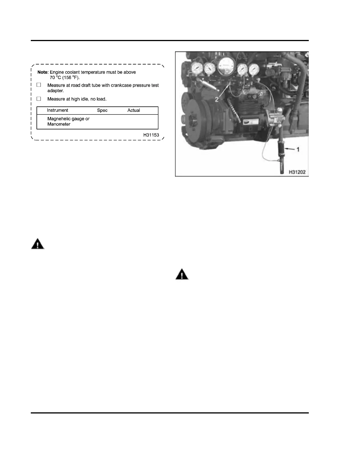
Figure 334 Test line connection to magnehelic
gauge
1. Crankcase pressure test adapter
2. Test line with pressure fitting
6. Install crankcase pressure test adapter to road
draft tube.
NOTE: If the engine has a breather extension
tube, the extension tube must be removed before
testing.
WARNING: To avoid serious personal injury,
possible death or damage to the engine or vehicle
– comply with the following:
• When routing test line , do not crimp the line,
run the line too close to moving parts, or let
the line touch hot engine surfaces.
• Test line must be free of fluid. Magnehelic
gauge can be damaged.
7. Connect test line from the crankcase pressure test
adapter to the magnehelic gauge on the gauge
bar or to a water manometer.
EGES-270-1
Read all safety instructions in the "Safety Information" section of this manual before doing any proced ures.
Follow all warnings, cautions, and notes.
©August 2008 Navistar, Inc.
 Loading...


