360 7 ELECTRONIC CONTROL SYSTEMS DIAGNOSTICS
EBP C ircuit Operation
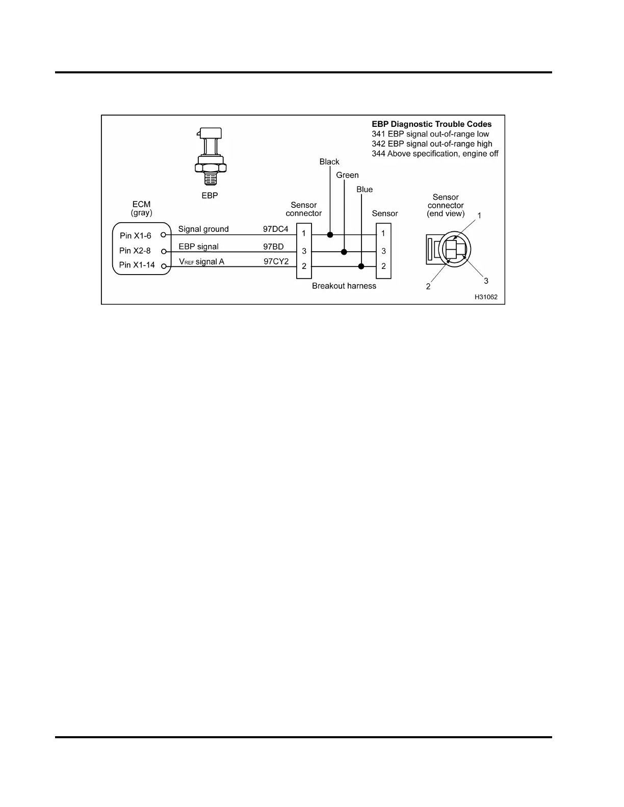
Figure 413 EBP circuit diagram
The EBP sensor is supplied with a 5 V reference
voltage at Pin 2 from ECM Pin X1–14. The EBP
sensor is grounded at Pin 1 from ECM Pin X1–6. The
EBP sensor returns a variable voltage sign al from P in
3toECMPinX2–8.
Fault Detection / Management
When the E BP signal voltage is d et ected out of range
high or low, the ECM will cause the engine to ignore
the EBP signal. The EGR valve will c lose and the
ECM will rely on the VGT pre-programmed values.
EBP Diagnostic Trouble Codes (DTCs)
DTCs are read using the EST or by counting the
flashes from the amber and red ENGINE lamp.
DTC 341
EBP signal o ut -o f -ra n ge low
• DTC 341 is set by the ECM when the EBP signal
is less than 0.039 V for more than 0.5 second.
• DTC 341 can be set due to an open or short to
ground on the signal circuit, a failed EBP sensor
or an open V
REF
circuit or V
REF
short to ground.
• When DTC 341 is active the amber ENGINE lamp
is illuminated.
DTC 342
EBP signal out-of-range high
• DTC 342 is set by the ECM when the EBP signal
is more than 4.9 V for more than 0.5 second.
• DTC 342 can be set due to a signal c ircuit shorted
to V
REF
or B+, or a failed EBP sensor.
• When DTC 342 is active the amber ENGINE lamp
is illuminated.
DTC 344
Above specification, engine off
• DTC 344 is set by the ECM when the exhaust
back pressure is greater than expected with the
key-on engine-o ff.
• DTC 344 can be set due to a plugged EBP sensor,
a restriction in the tube leading to the sensor, an
open signal ground, or a failed EBP sensor. To
check for possible restriction, remove the sensor
and tube and inspect for carbon deposits.
• When DTC 344 is active the amber ENGINE lamp
is illuminated.
EGES-270-1
Read all safety instructions in the "Safety Information" section of this manual before doing any procedures.
Follow all warnings, cautions, and notes.
© August 2008 Navistar, Inc.
 Loading...


