7 ELECTRONIC CONTROL SYSTEMS DIAGNOSTICS 315
BAP Circuit Operation
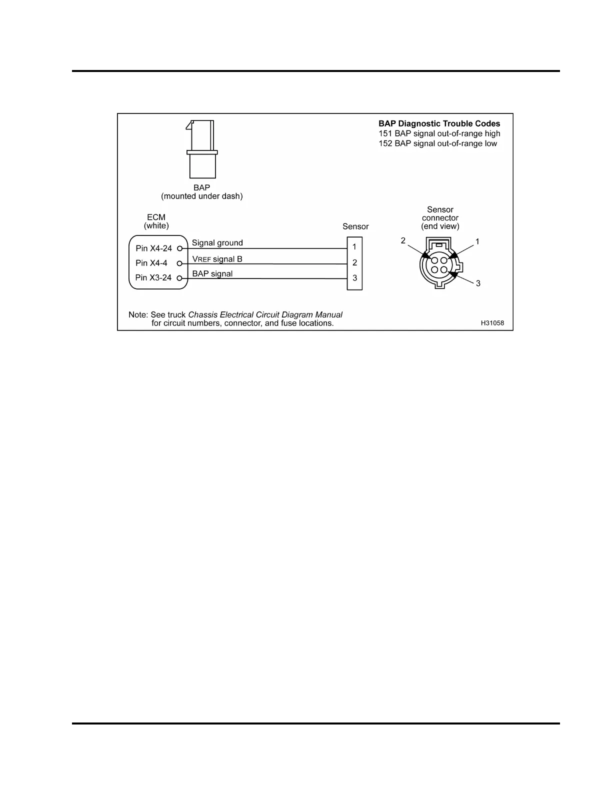
Figure 384 BAP circuit diagram
TheBAPsensorissuppliedwitha5Vreference
voltage at Pin 2 from ECM Pin X4–4 . The BAP
sensor is grounded at Pin 1 from ECM Pin X4–24.
The BAP sensor returns a variable voltage signal
from Pin 3 to ECM at Pin X3–24.
Fault Detection / Management
When the E CM detects the BAP volt ag e signal out of
range high or low, the ECM will ignore the BAP signal
and use the Manifold Absolute Pressure (MAP) signal
generated at low idle as an indication of barometric
pressure. When a MAP fault is detected, the BAP
signal will default to barometric pressure at sea level,
101kPa(29.8inHg).
BAP Diagnostic Trouble Codes (DTCs)
DTCs are read using the EST or by counting the
flashes from the amber and red ENGINE lamp.
DTC 151
BAP signal out-of-range high
• DTC 151 is set when the BAP signal is greater
than 4.95 V for more than 0.5 second.
• DTC 151 can be set when the signal circuit is
shortedtoV
REF
or B+ or a failed BAP sensor.
• When DTC 151 is active the amber ENGINE lamp
is illuminated.
DTC 152
BAP signal out-of-range low
• DTC 152 is set when the BAP signal is less than
1.0 V for more than 0.5 second.
• DTC 152 can be set when the signal circuit is
shorted to ground or open, V
REF
is shorted to
ground, or a failed BAP sensor.
• When DTC 152 is active the amber ENGINE lamp
is illuminated.
Tools
• EST with MasterDiagnostics® software
• EZ-Tech® interface cable
• Digital Multimeter (DMM)
• Breakout Box
EGES-270-1
Read all safety instructions in the "Safety Information" section of this manual before doing any procedures.
Follow all warnings, cautions, and notes.
© August 2008 Navistar, Inc.
 Loading...


