344 7 ELECTRONIC CONTROL SYSTEMS DIAGNOSTICS
Brake Shut-off Valve Pin-Point Diagnostics (ECM
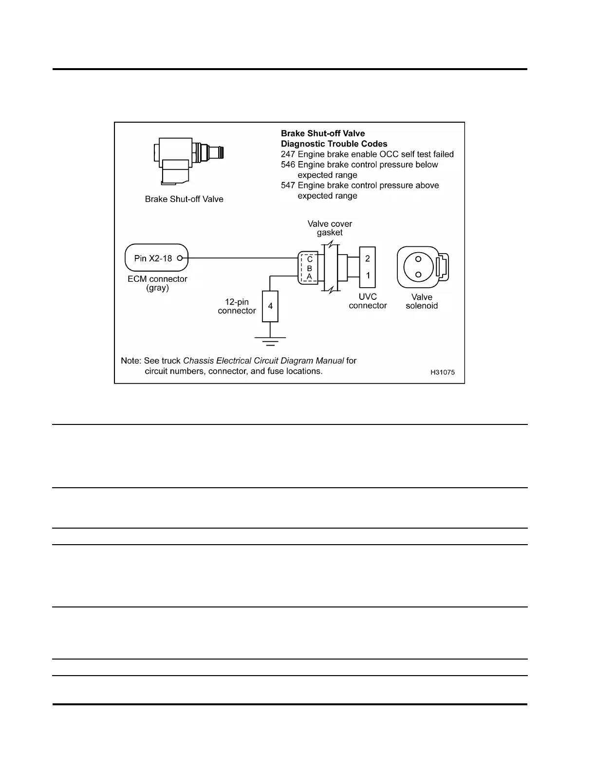
to brake valve – valve cover removed)
Figure 401 Brake S hut-off Valve circuit diagram
NOTE: Complete all pin-point diagnostics (ECM to valve cover gasket connector) before removing
valve cover for under-valve-cover diagnostics.
• Turn the ignition switch to OFF before disconnecting engine wiring harness connectors from components.
• See truck Chassis Electrical Circuit Diagram Manual for circuit numbers, connector and fuse locations.
Actuator Control Voltage C
heck at UVC Connector (Remove valve cover following procedure in the
Engine Service Manual.
Disconnect UVC connector from valve. Use the Terminal Test Adapter Kit to connect
the 500 Ohm Resistor har
ness to the UVC connector Pin 2 and ground. Turn the ignition switch to ON.)
Test Point
Spec Comment
2to1 0Vto0.25V
If > 0.25 V, continue with next test point, 2 to chassis
ground.
2tochassisgnd 0Vto0.25V
If > 0.25 V, con trol
wireisshortedtoV
REF
or B+.
1tochassisgnd 0Vto0.25V
If > 0.25 V, ground wire is shorted to V
REF
or B+.
Output State Test - Signal Check at UVC Connector (Disconnect UVC connector from valve. Use the
Terminal Test Adapter K it to connect the 500 Ohm Resistor harness to the UVC connector Pin 2 and ground.
Run the Output State Tests. For help, see “Diagnostic Software Operation” in Section 3 (page 68) for
procedure to run the Low and High Output State Tests. Measure across adapter and ground.)
Test State/Po
int
Setting/Spec Comment
EGES-270-1
Read all safety instructions in the "Safety Information" section of this manual before doing any procedures.
Follow all warnings, cautions, and notes.
© August 2008 Navistar, Inc.
 Loading...


