7 ELECTRONIC CONTROL SYSTEMS DIAGNOSTICS 501
MAP C ircuit Operation
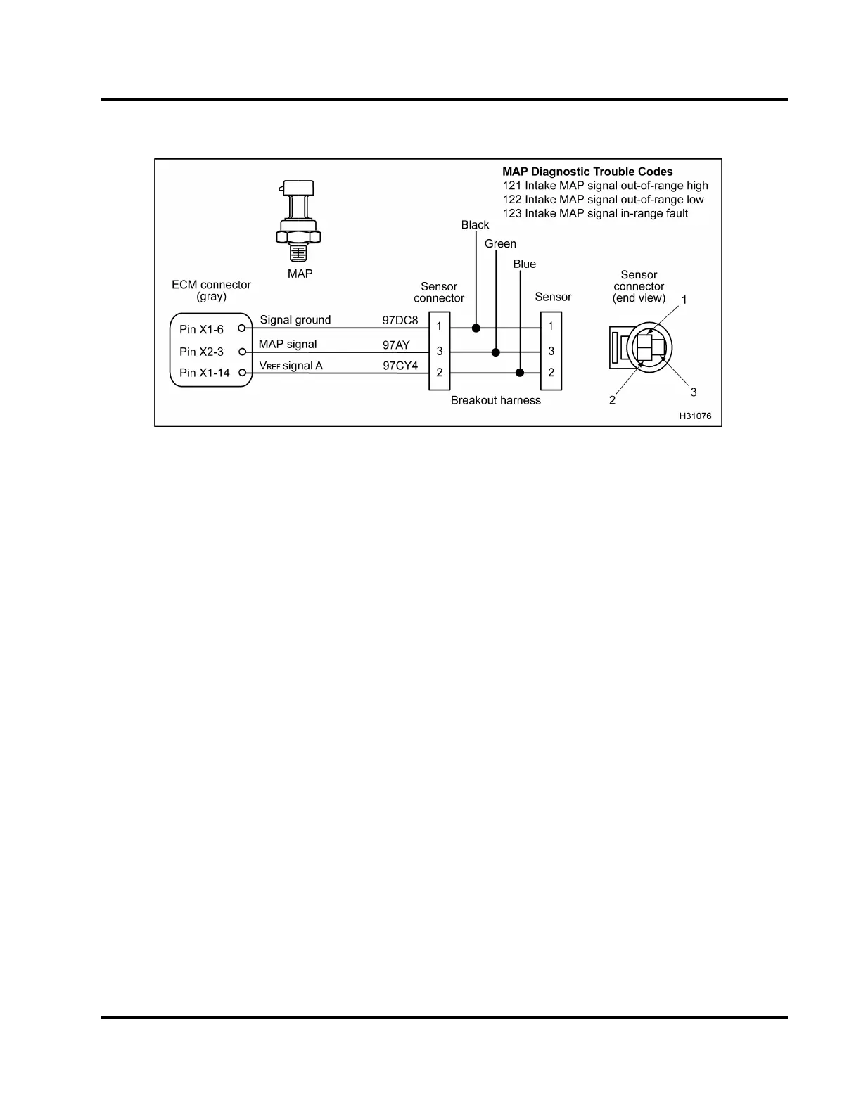
Figure 484 MAP circuit diagram
The MAP sensor is supplied with a 5 V reference
voltage at Pin 2 from ECM Pin X1–14. The MAP
sensor is grounded at Pin 1 from ECM Pin X1–6. The
MAP sensor returns a variable voltage signal from Pin
3toECMPinX2–3.
Fault Detection / Management
The ECM will ignore the MAP signal when the signal
is detected to be out of range o r an incorrect value is
read. The engine will continue to operate based on
estimate d values.
MAP Diagnostic Trouble Codes (DTCs)
DTCs are read using the EST or by counting the
flashes from the amber and red ENGINE lamp.
DTC 121
Intake MAP signal out-of-range high
• DTC 1 21 is se t by the ECM when the MAP signa l
is greater than 4.9 V for more than 0.4 second.
• DTC 121 can be set due to a signal circuit short
to V
REF
or B+ or a failed MAP sensor.
• When DTC 121 is active the amber ENGINE lamp
is illuminate d.
DTC 122
Intake MAP signal out-of-range low
• DTC 122 is set by ECM when the MAP signal is
less than 0.039 V for more than 0.4 second.
• DTC 122 can be set due to an open or short to
ground on the signal circuit, a failed MAP sensor
or an open V
REF
circuit or V
REF
short to ground.
• When DTC 122 is active the amber ENGINE lamp
is illuminated.
DTC 123
Intake MAP signal in-range fault
• DTC 123 is set by ECM when the MAP signal is
greater than 115 kPa (17 psi) absolute at low idle.
• DTC 123 can be set due to a restricted or plugged
sensor inlet, open signal ground, V
REF
shorted to
voltage source above 5.5 V, biased circuit, or a
failed MAP sensor.
• When DTC 123 is active the amber ENGINE lamp
is illuminated.
Tools
• EST with MasterDiagnostics® software
• EZ-Tech® interface cable
• Digital Multimeter (DMM)
• 3-Banana Plug Harness
• 500 Ohm Resistor Harness
EGES-270-1
Read all safety instructions in the "Safety Information" section of this manual before doing any procedures.
Follow all warnings, cautions, and notes.
© August 2008 Navistar, Inc.
 Loading...


