174 5 HARD START AND NO START DIAGNOSTICS
11. Main Power Relay to ECM
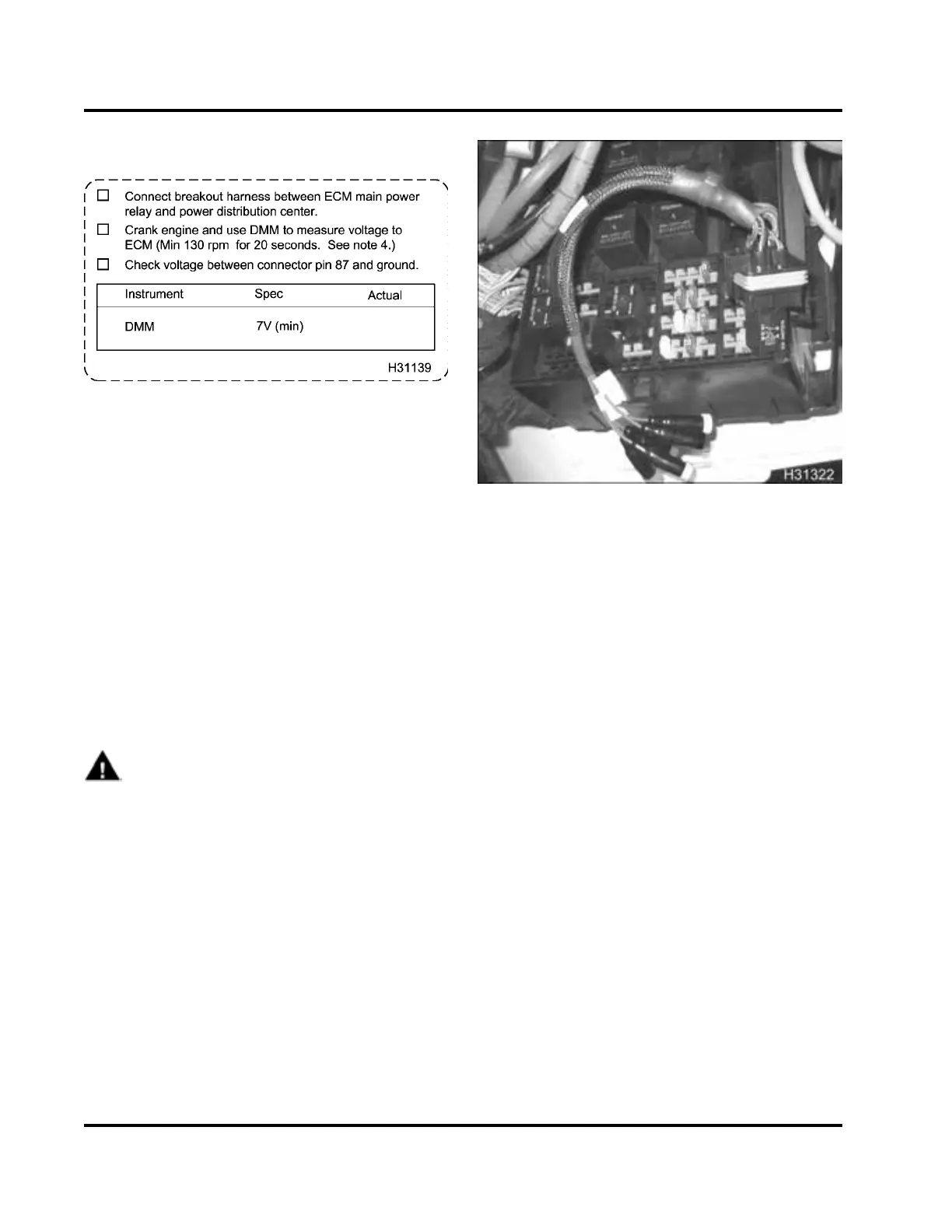
Figure 203
Purpose
To determine correct power supplied to operate the
ECM
The ECM requires 7 V minimum for correct operation.
Voltage Measurement with Breakout Harness at
Main Powe r Relay
Tools
• Relay Breakout Harness
•DMM
Procedure
WARNING: To avoid serious personal injury,
possible death, or damage to the engine or
vehicle, read all safety instructions in the “Safety
Information” section of this manual.
NOTE: Batteries must be fully charged before doing
the following steps.
1. Turn the ignition switch to OFF and ensure all
accessories are turned off.
Figure 204 R el ay Breakou t Harness to power
distribution center
2. Connect Relay Breakout Harness between ECM
main power relay and power distribution center or
chassis harness depending on application.
NOTE: Depending on application, the relay could
be one of two kinds. Check power distribution
center or cab cowl.
3. Connect D M M POS to lead 87 and NEG t o ground
terminal on cowl.
4. Crank engine for 20 seconds and measure
voltage.
5. Record the lowest voltage on Diagnostic Form.
• If the voltage is below 7 V, the ECM main
power relay may be reset ting, due to low
voltage and current from the batteries, or
problems in th e ignition circuit a n d power
feed circuits. See Electronic Control Module
Power (ECM PWR) in Section 7 (page 381).
• If the voltage is above 7 V, continue with Hard
Start and No Start Diagnostic tests.
NOTE: Results can be above 7 V, but there
may be a problem between the main power
relayandtheECM.IfaHardStart/NoStart
problem remains after all Diagnostic Form tests
are comp le te, do Voltage Mea su rement a t ECM
with Breakout Box.
EGES-270-1
Read all safety instructions in the "Safety Information" section of this manual before doing any proced ures.
Follow all warnings, cautions, and notes.
©August 2008 Navistar, Inc.
 Loading...


