316 7 ELECTRONIC CONTROL SYSTEMS DIAGNOSTICS
BAP Pin-Point Diagnostics
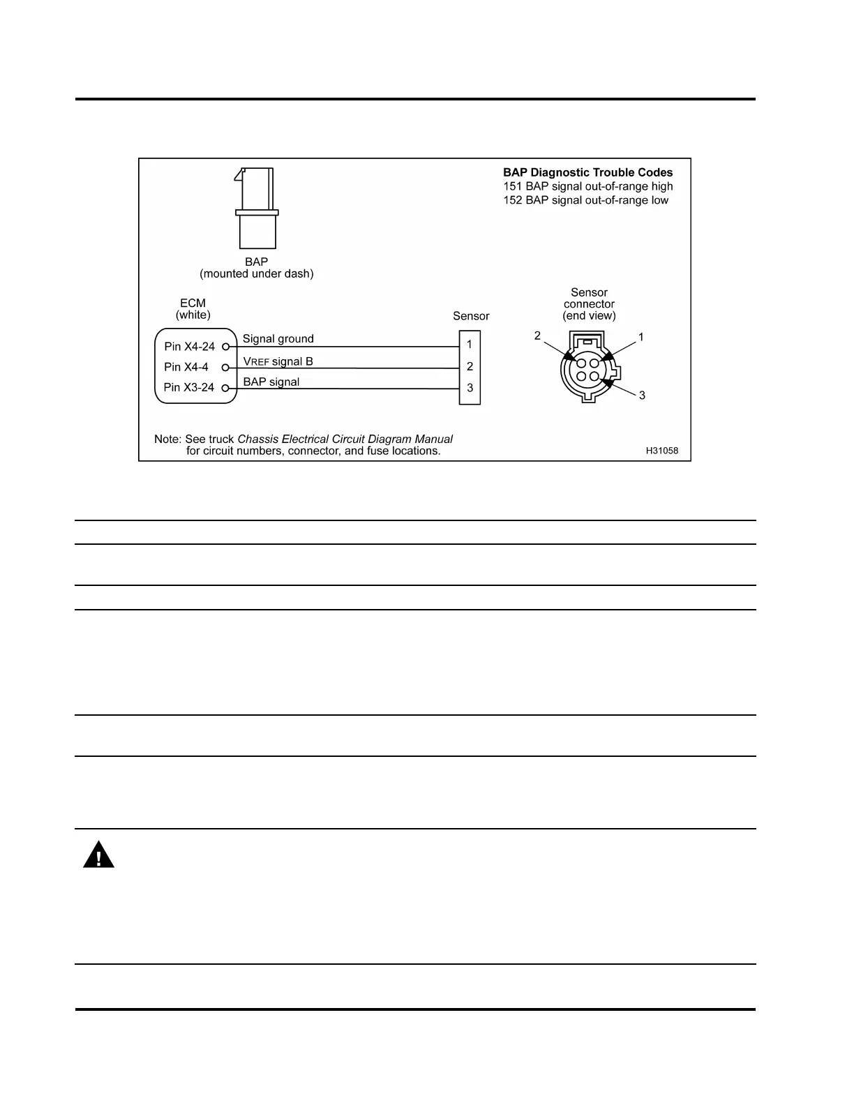
Figure 385 BAP circuit diagram
NOTE: See truck Chassis Electrical Circuit Diagram Manual for circuit numbers, connector and fuse locations.
Connector Voltage Checks to Grou
nd (Disconnect harness from sensor. I nspect for bent pins or
corrosion. Turn th e ignition swi
tch to ON.)
Test Point
Spec Comment
1 to gnd 0 V to 0.25 V
If > 0.25 V, check ground circuit for open or high resistance. Check
signal ground for short to V
REF
or B+.
2tognd 5V±0.5V
If voltage is not to spec, V
REF
circuit is shorted to ground, shorted
to B+, or open.
3 to gnd 0 V to 0.25 V
If voltage > 0.25 V, signal circuit is shorted to V
REF
or B+.
Connector Resistance Checks to ECM Chassis Ground (Turn the ignition switch to OFF. Disconnect
chassis connector 9260
1
.)
1 to Pin A (9260) < 5 Ω If > 5 Ω, check for open
signal ground.
2 to Pin A (9260) > 1 kΩ If < 1 kΩ,checkforV
REF
short to ground.
3 to Pin A (9260) > 1 kΩ If < 1 kΩ, check for signal s ho rt to ground.
WARNING: To avoid serious personal injury, possible death, or damage to the engine or vehicle,
always disconnect main negative battery cable first. Always connect the main negative battery cable
last.
Connector Resistance Checks to Chassis Ground (Turn the ignition switch to OFF. Disconnect chassis
connector 9260
1
. Disconnect negative battery cable. Disconnect harness from sensor. Use disconnected
negative battery cable for ground test point.)
1 to gnd cable
> 500 Ω If < 500 Ω , chec
k for short to ground.
EGES-270-1
Read all safety instructions in the "Safety Information" section of this manual before doing any procedures.
Follow all warnings, cautions, and notes.
© August 2008 Navistar, Inc.
 Loading...


