7 ELECTRONIC CONTROL SYSTEMS DIAGNOSTICS 407
EFP Circuit Operation
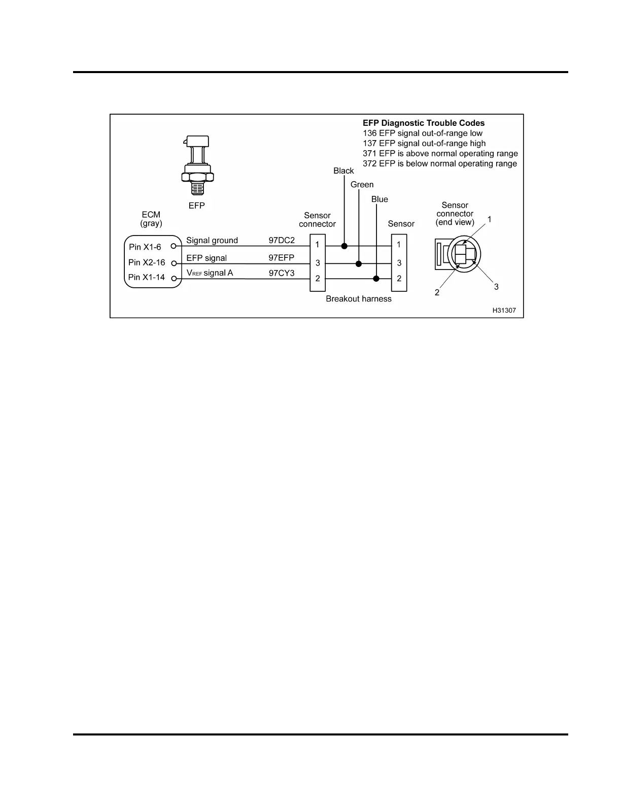
Figure 438 EFP circuit diagram
The EFP sensor is supplied with a 5 V r
eference
voltage at Pin 2 from ECM Pin X1–14.
The EFP
sensor is grounded at Pin 1 from E C
M Pin X1–6. The
EFP sensor returns a variable vo
ltage signal from Pin
3toECMPinX2–16.
Fault Detection / Management
The ECM will ignore the EFP sig
nal when the signal
is dete cted to be out of range
or an incorrect value is
read.
EFP Diagnostic Trouble Code
s (DTCs)
DTCs are read using the EST
or by counting the
flashes from the amber and
red ENG INE lamp.
DTC 136
EFP signal out-of-range l
ow
• DTC 136 is set by ECM when th
e EFP signal is
less than 0.039 V for mor
e than 0.35 second.
• DTC 136 can be set due to an
open or short to
ground on the signal cir
cuit, a failed EFP sensor
or an open V
REF
circuit
or V
REF
short to ground.
• When DTC 136 is active th
e amber ENGINE lamp
is not illuminated.
DTC 137
EFP signal out-of-range high
• DTC 137 is set by the ECM when the EFP si
gnal
is greater than 4.9 V for more than 0.
35 second.
• DTC 137 can be set due to a signal circ
uit short
to V
REF
or B+ or a failed EFP senso
r.
• When DTC 137 is active the amber EN
GINE lamp
is not illuminated.
DTC 371
EFP is above normal operating ran
ge
• DTC 371 is set by ECM when measur
ed fuel
pressure is greater than expe
cted pressure by
100 kPa (15 psi) for more than 6
0 seconds.
• DTC 371 can be set due to debris
in fuel regulator
valve, failed fuel regulato
r valve, open signal
ground, V
REF
shortedtoavol
tage source greater
than 5.5 V, bias high circ
uit, or failed EFP sensor.
• When DTC 371 is active the a
mber FUEL FILTER
lamp will not illum inate
EGES-270-1
Read all safety instructions in the "Safety Information" section of this manual before doing any procedures.
Follow all warnings, cautions, and notes.
© August 2008 Navistar, Inc.
 Loading...


