288 7 ELECTRONIC CONTROL SYSTEMS DIAGNOSTICS
Vehicle Mounted Components
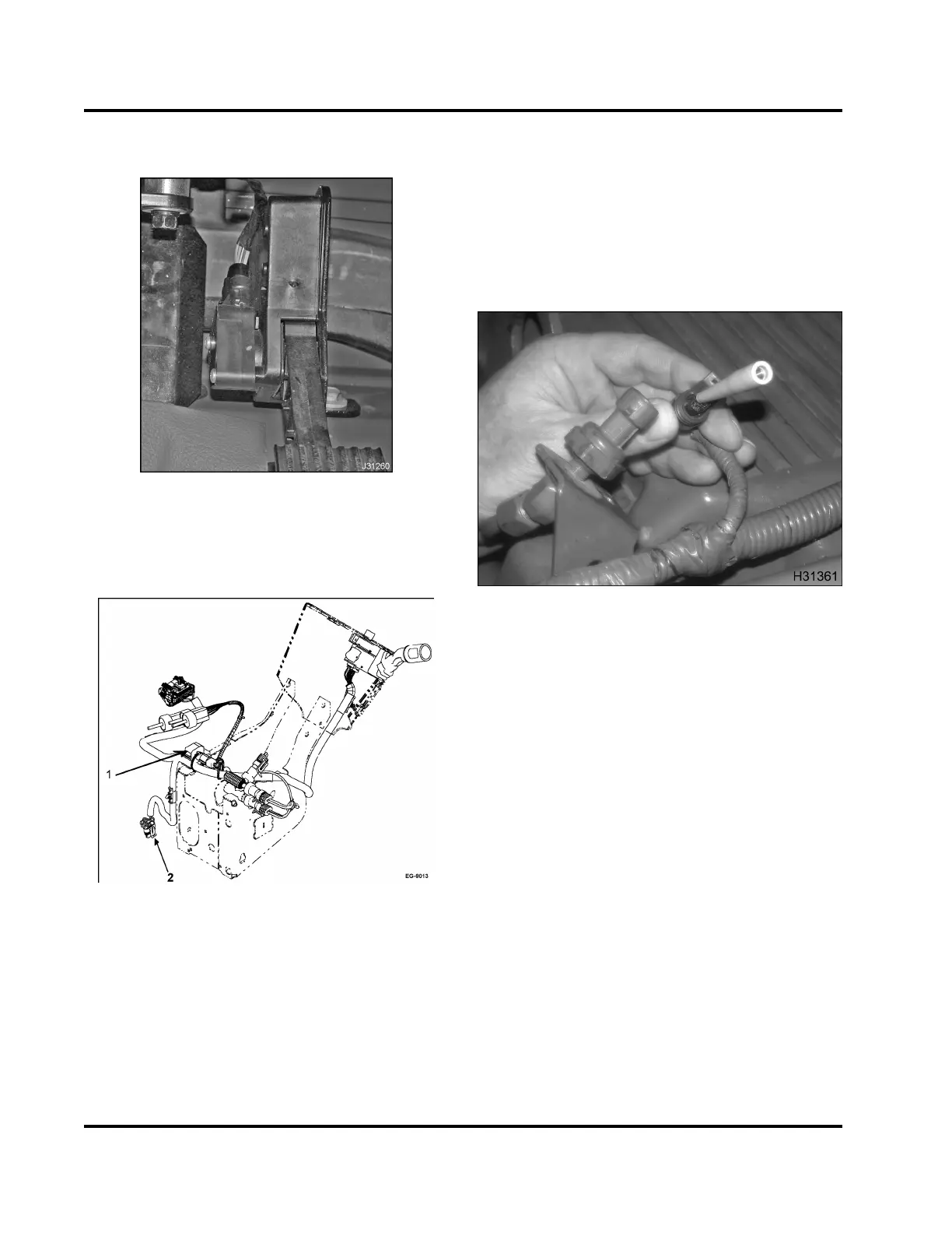
Figure 367 APS/IVS sensor
The APS/IVS sensor is located ab ove the a
ccelerator
pedal.
Figure 368 Under the dashboard sensors
1. Barometric Absolute Pressure (BAP) sensor
2. Accelerator Pedal Position and Idle Validation
Connector (APS/IVS)
The B AP sensor is located in the cab of the vehicle.
Diagnostic Procedures for Sensors
and Actuators
PinGripInspection
Figure 369 Pin grip check
1. Disconnect the harness c on nector from the
sensor or actuator.
2. Inspect for corrosion, bent pins, spread pins, or
conditions that could cause a loose or intermittent
connection.
3. Check the pin grip in the female pin by inserting
the correct tool from Terminal Tes t Adapter Kit.
EGES-270-1
Read all safety instructions in the "Safety Information" section of this manual before doing any procedures.
Follow all warnings, cautions, and notes.
© August 2008 Navistar, Inc.
 Loading...


