494 7 ELECTRONIC CONTROL SYSTEMS DIAGNOSTICS
IPR (Injection Pressure Regulator )
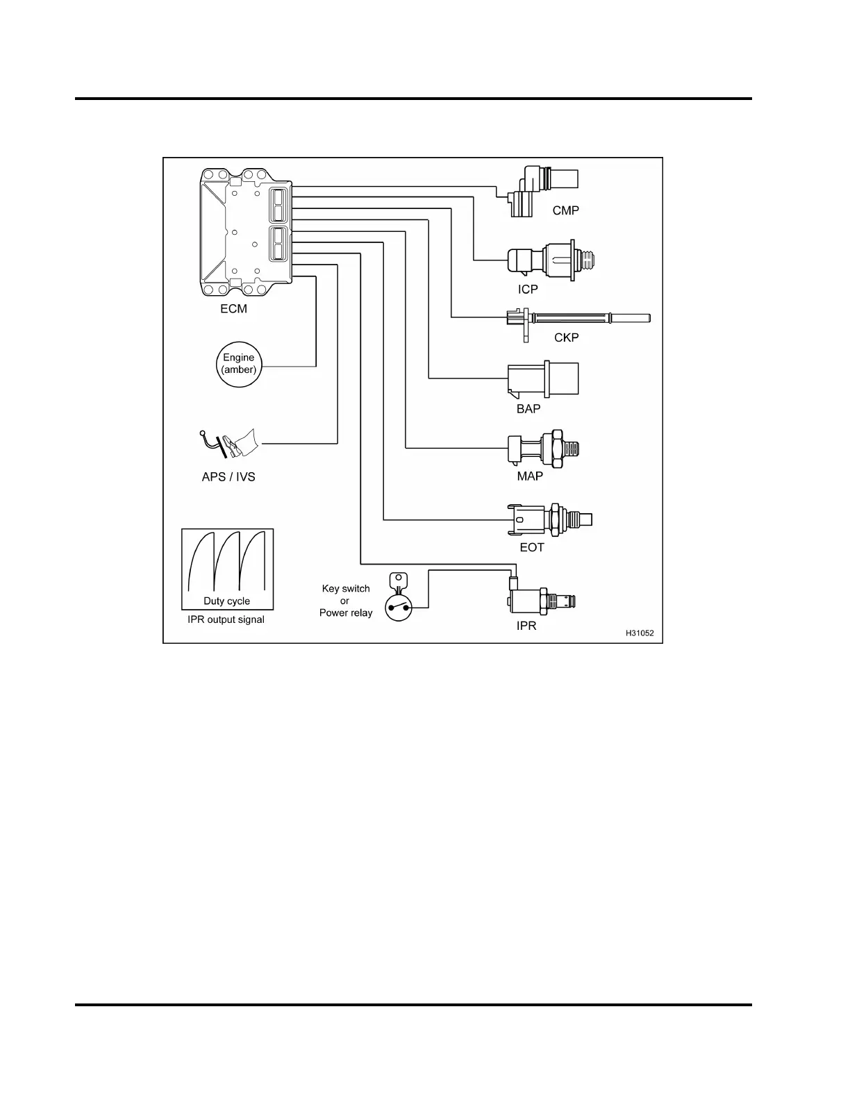
Figure 480 Function diagram for the IPR
The function diagram for the IPR includes the
following:
•IPR
• Engine Oil Temperature (EOT) sensor
• Injection Control Pressure (ICP) sensor
• Manifold Absolute Pressure (MAP) sensor
• Barometric Absolute Pressure (BAP) sensor
• Camshaft Position (CMP) sensor
• Crankshaft Position (CKP) sensor
• Accelerator Position / I dle Validation (APS/IVS)
sensor
• Electronic Control Module (ECM)
Function
The IPR valve controls oil pressure in the
high-pressure injection control system that actuates
the injectors. The IPR valve consists of a solenoid,
poppet, and a spool valve assembly. The IPR is
mounted in the body of the high-pressure pump. The
ECM regulates ICP by controlling the ON/OFF time
of the IPR solenoid. An increase or decrease in the
ON/OFF time positions the poppet and spool v alve
inside the IPR and maintain s pressure in the ICP
system or vents pressure to the oil sump through the
front cover.
NOTE: The engine may not operate with an IPR fault,
depending on the mode of failure.
EGES-270-1
Read all safety instructions in the "Safety Information" section of this manual before doing any procedures.
Follow all warnings, cautions, and notes.
© August 2008 Navistar, Inc.
 Loading...


