384 7 ELECTRONIC CONTROL SYSTEMS DIAGNOSTICS
ECM PWR Pin-Point Diagnostics
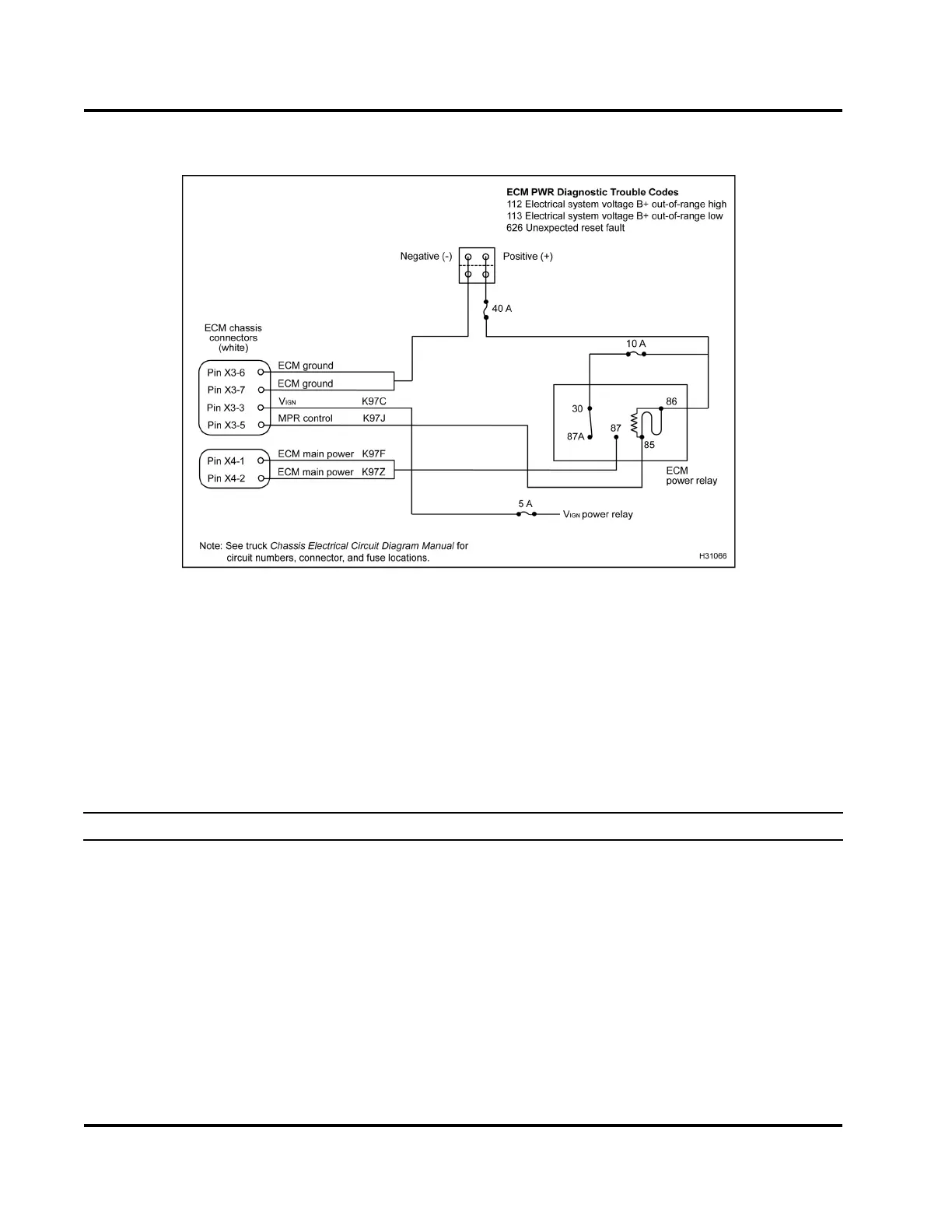
Figure 426 ECM PWR circuit diagram
The ECM PWR circuit requires the use of vehicle circuit diagrams. See truck Chassis Electrical Circuit
Diagram Manual for circuit numbers, connector and fuse locations.
CAUTION: To avoid engine damage, turn the ignition switch to OFF before removing main power relay or any
ECM connector supplying power to the ECM. Failure to turn the ignition switch to OFF will cause a voltage
spike and damage to electrical components.
Voltage Checks at ECM Power Relay Socket – Key-On Engine-Off (Follow tests in order. Check with
relay breakout harness connected to relay and power distribution center and turn the ignition switch on.
Inspect for bent pins or corrosion.)
Test Point
Spec Comment
86 to gnd 12 V ±1.5 V
Continuous voltage. If no voltage, check power circuits from batteries
through fuse. If fuse is blown, check for short to ground. If fuse is good,
check for open between Pin 30 and B+. See truck Chassis Electrical
Circuit Diagram Manual for relay and fuse locations.
30 to gnd 12 V ± 1.5 V
Continuous voltage. If no voltage, check fuses. If fuse is blown, check
for short to ground. If fuse is good, check for open between Pin 30 and
B+. See truck Chas sis Electrical Circuit Diagram Manual for fuse and
relay locations.
EGES-270-1
Read all safety instructions in the "Safety Information" section of this manual before doing any procedures.
Follow all warnings, cautions, and notes.
© August 2008 Navistar, Inc.
 Loading...


