7 ELECTRONIC CONTROL SYSTEMS DIAGNOSTICS 355
CMP Sensor (Camshaft Position)
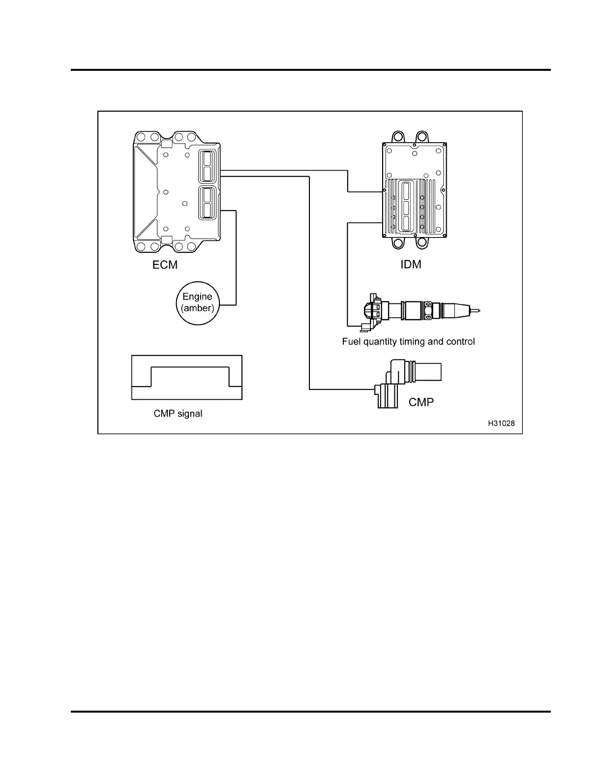
Figure 409 Function diag
ram for the CMP sensor
The function diagram f
or the CMP sensor includes the
following:
• CMP sensor
• Electronic Control M
odule (ECM)
• Injector Drive Modul
e(IDM)
• Fuel Injector
• ENGIN E lamp (am ber)
The CMP sensor provid
es the ECM with a signal that
indicates camshaft
position. As the cam rotates, the
sensor identifies th
e position of the cam by locating
a peg on the cam. The CMP
is installed in the front
cover, above and to the
right of the water pump pulley.
Camshaft speed is cal
culated from the frequency of
the CMP sensor sig na
l. Diagnostic information on the
CMP input signal is
obtained by performing accuracy
checks on signal le
vels, frequency, and duty cycle with
software strateg
ies.
NOTE: The short CM
P s ensor, used with
International®
DT 466, DT 570, and HT 570 diesel
engines, is the
Crankshaft Position (CKP) sensor
used with other
International® diesel engines.
EGES-270-1
Read all safety instructions in the "Safety Information" section of this manual before doing any procedures.
Follow all warnings, cautions, and notes.
© August 2008 Navistar, Inc.
 Loading...


